μ
PS-SP Series 3:3 Phase, 10 – 60 kVA, 3 X 208 Vac, 60 Hz, 192 Vdc
iv
6.
COMMUNICATIONS............................................................................................ 34
6.1
RS232 Interface ......................................................................................... 34
6.2
The Alarm Interface .................................................................................. 35
6.3
Remote Monitor Box (Optional)............................................................... 36
6.3.1
Connecting the Monitor Box to the UPS......................................... 37
7.
TROUBLESHOOTING......................................................................................... 38
8.
SITE PREPARATION .......................................................................................... 41
8.1
Installation Considerations...................................................................... 41
8.2
Electrical Wiring........................................................................................ 42
8.3
Terminal Connections .............................................................................. 44
9.
INSTALLATION ................................................................................................... 45
9.1
Accessibility.............................................................................................. 45
9.2
Circuit Breakers ........................................................................................ 45
9.3
Installation of Standalone UPS................................................................ 47
9.3.1
Wiring/Cabling Instructions ............................................................. 47
9.3.2
External Battery Cabinet .................................................................. 48
9.3.3
Turning On the UPS for the First Time ........................................... 49
9.4
Installation of Decentralized Parallel Systems....................................... 51
9.5
Parallel Start-Up ........................................................................................ 52
9.5.1
Decentralized (2 UPSs only) ............................................................ 52
10.
TECHNICAL SPECIFICATIONS ......................................................................... 54
LIST OF FIGURES
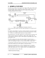
Figure 1: Schematic Diagram of the Operation of the UPS................................................. 2
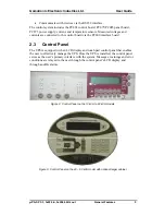
Figure 2: Control Panel on the 10 kVA to 60 kVA models................................................... 5
Figure 3: Control Panel on the 40 – 60 kVA model with optional larger cabinet .............. 5
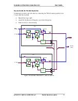
Figure 4: Decentralized Parallel µPS - cable connections ................................................... 9
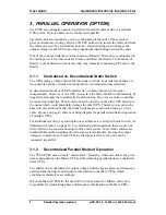
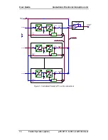
Figure 5: Centralized Parallel µPS - cable connections ..................................................... 10
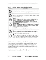
Figure 6: Control panel on the standard cabinet (10kVA to 60kVA models) .................. 11
Figure 7: Control panel on the larger cabinet (optional for 40–60KVA models)............ 16
Figure 8: LOG Messages Structure ..................................................................................... 21
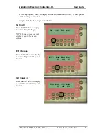
Figure 9: Accessing the Log on the standard cabinet ...................................................... 21
Figure 10: Accessing the Log on the large cabinet ........................................................... 22
Figure 11: Active Current Sharing ....................................................................................... 26
Figure 12: Voltage Correction .............................................................................................. 26
Figure 13: LED Indicators on the standard cabinet ........................................................... 27
Figure 14: LED Indicators on the optional larger cabinet ................................................. 27
Figure 15: Remote Monitor Box ........................................................................................... 36
Figure 16: External circuit breakers .................................................................................... 42
Figure 17: Terminal Connections ......................................................................................... 44
Figure 18: Circuit breakers on the 10-20KVA models ....................................................... 45
Figure 19: Circuit breakers on the 30-60 kVA models ....................................................... 46
Figure 20: Connecting the external battery cabinet ........................................................... 48
Summary of Contents for PS-SP Series
Page 1: ......


