background image

Gamatronic Electronic Industries Ltd.  

User Guide 


µ

PS-SP 3:3, 3x220 in, 3x208 60 Hz out 

Control Panel & Indicators 

23


Table 1:  Log Variables  


Event 

LOG Variable 

Overload 

Sum of currents in all phases 

Inverter fault 

V

inv 

(average inverter voltage) in all phases 

Bypass fault 

V

byp

 (average bypass voltage) in all phases where 

there is a bypass voltage fault 
 or 
Hz (Frequency) where there is a bypass frequency 
fault 

Input fault 

Average V

in

 on all phases 

High temperature 

Temperature °C 

Rectifier fault, battery low 

DC voltage 

Other fault 

Average V

out

 for all phases 


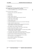
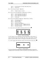
Faults are represented as a hexadecimal word comprising 16 bits: 

Bit 0:  1 = Overload 
Bit 1:  Inverter 
Bit 2:  Bypass 
Bit 3:  Rectifier 
Bit 4:  Input 
Bit 5:  Phase sequence 
Bit 6:  Temperature 
Bit 7:  Battery test failure 
Bit 8:  Output 
Bit 9:  Load on bypass 
Bit 10: Circulation (for parallel) 
Bit 11: Slave receive failure (parallel only) 

For example, fault 0009H = 0000000000001001 binary which translates as overload and 
battery test failure. 

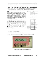
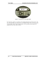
SET (Time)  

Pressing this button sets the unit’s real-time clock (see “Setting the Real Time Clock” on 
page 33. 

Summary of Contents for PS-SP Series

Page 1: ......

Page 2: ...rves the right without prior notice or liability to make changes in equipment design or specifications Information supplied by Gamatronic Electronic Industries Ltd is believed to be accurate and relia...

Page 3: ...PARALLEL OPERATION OPTION 8 3 1 1 Centralized vs Decentralized Static Switch 8 3 1 2 Decentralized Parallel Mode of Operation 8 4 CONTROL PANEL INDICATORS 11 4 1 The Control Panel on the Standard Cab...

Page 4: ...S 2 Figure 2 Control Panel on the 10 kVA to 60 kVA models 5 Figure 3 Control Panel on the 40 60 kVA model with optional larger cabinet 5 Figure 4 Decentralized Parallel PS cable connections 9 Figure 5...

Page 5: ...37 Table 6 Trouble Shooting and Problem Solving 38 Table 7 PC Board Check Points Voltage Ranges 40 Table 8 External circuit breakers required minimum ratings 43 Table 9 Wiring requirements 43 Table 1...

Page 6: ...PS SP Series 3 3 Phase 10 60 kVA 3 X 208 Vac 60 Hz 192 Vdc vi This page left blank deliberately...

Page 7: ...cated on the electronic cabinet or directly to the grounding circuit Use the UPS only for its intended purpose Allow only qualified technicians to service the UPS There are no user serviceable compone...

Page 8: ...l load When backup service is provided when there is a power breakdown in the mains the UPS is powered by batteries and maintains a constant output voltage supply The system informs the operator by me...

Page 9: ...ckup the same load Two topologies are supported centralized and decentralized With a decentralized parallel system each UPS has its own static switch in which case two systems can be connected in para...

Page 10: ...nterruption or disturbance When the UPS is in BYPASS mode the load draws power directly from the mains bypassing the inverter The ST SW automatically switches the load back to the inverter when invert...

Page 11: ...rol board via the PC800 interface board 2 3 Control Panel The UPS is equipped with an LCD display and touch pad control panel that enables the user to effectively manage the UPS Once the UPS is instal...

Page 12: ...via the LCD display or optionally through the RS232 communications port 2 7 Communications The UPS relays all the measured data and events of the log file through an RS232 communications port to a hos...

Page 13: ...hese terminals are labeled EMERG OFF or EPO N C The Emergency Power Off terminals should be connected by a normally closed 48V 0 1A mushroom type pushbutton Pressing the pushbutton opens the contact a...

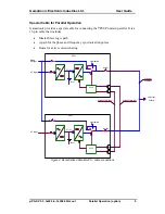
Page 14: ...gered and supply the load directly from the mains Two or more units would then be connected in parallel This would connect the inverter of the other UPS directly to the mains which could potentially d...

Page 15: ...arallel It is a 15 pin cable that includes Master Slave logic path A path for the phase and frequency syncronization pulses Buses for active current sharing To Load Output AC Output UPS 1 Power Bus DC...

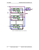
Page 16: ...ss Reference AC Output AC Input To Load Battery DC link Bypass AC Input Bypass Reference DC link UPS 1 DC link UPS 2 Bypass Reference Control AC Output Output Contactor AC Input Power Bus Battery Batt...

Page 17: ...abinet used for the 10 60KVA models differs in appearance from the console of the larger cabinet an option for the 40 60 kVA models we discuss two control panels separately according to cabinet type T...

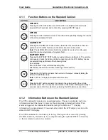
Page 18: ...ly performed at the following times Upon start up Every 200 hours of accumulated operating time After battery cabinet reconnection following a disconnection INV INV Pressing the INV button connects th...

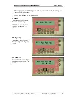
Page 19: ...nd current Sample LCD displays are presented below IN Input Press the IN button to display the unit s Input Voltage NOTE Input current current display is available as an option IN 230 230 231 B P Bypa...

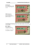
Page 20: ...the FREQ button to display the unit s Bypass and Inverter Frequency BYP FREQ 49 9Hz INV FREQ 49 9Hz The operating inverter frequency is determined by the bypass frequency when operating normally Othe...

Page 21: ...ibed on page 23 UPS OK 0 18 12 12 35 40 STAT Status Press the STAT button to display the unit s status and accumulated working time HHHHH MM SS For status and fault analysis see System Fault Diagnosti...

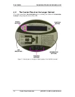
Page 22: ...out Control Panel Indicators 16 4 2 The Control Panel on the Larger Cabinet The control panel has 6 function buttons for controlling the unit and 12 information buttons for reporting the status of the...

Page 23: ...2 seconds and confirm the selection by pressing the B P INVbutton a second time When the UPS is in Bypass mode pressing the B P INV button connects the inverter to the output manually taking the UPS o...

Page 24: ...Input Press the IN button to display the unit s Input Voltage NOTE Input current current display is available as an option IN 230 230 231 B P Bypass Press the B P button to display the unit s Bypass V...

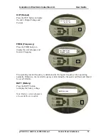
Page 25: ...the FREQ button to display the unit s Bypass and Inverter Frequency BYP FREQ 49 9Hz INV FREQ 49 9Hz The operating inverter frequency is determined by the bypass frequency when operating normally Othe...

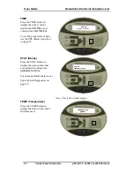
Page 26: ...roper time or date use the SET button described on page 23 UPS OK 0 01 11 14 23 01 STAT Status Press the STAT button to display the unit s status and accumulated working time HHHHH MM SS For status an...

Page 27: ...tup and shutdown AC input failure AC input restore a swich to Bypass or Battery mode or a return to Normal mode Each log entry is two screens long The first window to appear is the first part of the m...

Page 28: ...Accessing the Log on the large cabinet Each log entry requires 2 screens that can be navigated using the up and down arrows The first screen provides a description of the event with date and time The...

Page 29: ...ses High temperature Temperature C Rectifier fault battery low DC voltage Other fault Average Vout for all phases Faults are represented as a hexadecimal word comprising 16 bits Bit 0 1 Overload Bit 1...

Page 30: ...ized to the bypass Number of batteries connected in series Nominal capacity of each battery for use in calculating backup duration where the battery current meter option is installed DC shutdown volta...

Page 31: ...F Bit 1 Load supply 1 On bypass 0 On inverter Bit 5 Battery check 1 In progress 0 Pending To view fault condition details press the down arrow and 9 bytes are displayed on the panel Byte 1 shows input...

Page 32: ...3 1 Inverter under diagnosis Bit 4 1 Switching to inverter SRSW SCR is ON Bit 5 1 Switching to inverter SRSW SCR is OFF Bit 6 1 System in wait state To view the active current sharing status press the...

Page 33: ...operation of the UPS They are color coded so that the user can easily and quickly identify areas for concern Red indicates a fault or abnormal status usually associated with an audible alarm and gree...

Page 34: ...MEANING COLOR BYPASS Bypass Normal Green B P Output Connected to the Bypass Red OVERLOAD Overload Red BATTERY Battery Not Normal Red SYNC Synchronized Inverter Green CHARGER Charger Operating Green I...

Page 35: ...y cabinet 4 The UPS performs a self test that takes approximately one minute Verify that the UPS OFF message is displayed on the LCD display after the test is completed UPS OFF 5 Verify that both the...

Page 36: ...ge UPS OK appears on the LCD display and that NO RED LED is lit UPS OK 10 Turn ON the UPS Output circuit breaker 11 The UPS is ready for use and begins charging the batteries Connect the equipment to...

Page 37: ...ut first putting the UPS in BYPASS mode the red B P light must be lit For UPSs with the optional Bypass Isolation Transformer DO NOT turn off the Static Switch Bypass circuit breaker when using the Ma...

Page 38: ...ith the optional Bypass Isolation Transformer DO NOT turn off the Static Switch Bypass circuit breaker when using the Maintenance Bypass switch To deactivate MAINTENANCE BYPASS and restart the UPS 1 V...

Page 39: ...econds The UPS can now be turned on as described in Section 5 1 Turning the UPS ON on page 29 5 6 Setting the Real Time Clock The real time clock is composed of the date and time fields and may be set...

Page 40: ...rams for communication with a computer network optional LOCAL DIRECT CONNECTION 6 1 RS232 Interface The UPS supports standard UPS protocol Full information about the status of the UPS the value of its...

Page 41: ...Gamatronic Electronic Industries Ltd User Guide PS SP 3 3 3x220 in 3x208 60 Hz out Communications 35 6 2 The Alarm Interface The following diagram describes the Alarm Interface...

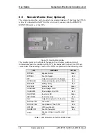
Page 42: ...ts LEDs are color coded The meaning of each of the LEDs is explained in the following table LED MEANING COLOR BYPASS Bypass Normal Green BYPASS Fault in Bypass Red B P Output Connected to the Bypass R...

Page 43: ...est ALARM OFF Silences the audible alarm Table 5 Control Buttons on Remote Monitor Panel 6 3 1 Connecting the Monitor Box to the UPS 1 Attach the back of the monitor box to the wall 2 The UPS PC908 bo...

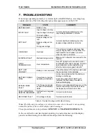
Page 44: ...load to bypass It returns automatically to normal operation only after the temperature goes below 55 BATT NOT CONNECT Battery is not connected Check the status of the battery switch and the connection...

Page 45: ...right and left panels Connnect DC voltmeter across C101 and wait for discharge to 5V Check for burned or damaged components Check all board connectors are secure Check IC2 on PC901 is securely seated...

Page 46: ...nic Electronic Industries Ltd PS SP 3 3 3x220 in 3x208 60 Hz out Troubleshooting 40 Table 7 PC Board Check Points Voltage Ranges BOARD CHASSIS CHECK POINT VOLTAGE PC 801 TP10 5V 5 PC 800 P13 1 12V 5 P...

Page 47: ...sufficient free space at the sides of the UPS for service accessibility For the 80K cabinet 20cm of free space is required at the sides of the UPS For the 20B cabinet 60 to 70 cm of free space is requ...

Page 48: ...separate conduit 2 Use of appropriately rated external circuit breakers on the lines from the electrical supply board to the UPS and from the UPS to the distribution board is critically important See...

Page 49: ...60 kVA 3 x 250 A 3 x 250 A 3 x 200 A 300 A Notes 1 S1 S2 S3 are 3 phase ac circuit breakers 2 S4 is a dc circuit breaker rated at 250 Vdc Table 9 Wiring requirements UPS Model Rectifier Input Bypass I...

Page 50: ...Electronic Industries Ltd PS SP 3 3 3x220 in 3x208 60 Hz out Site Preparation 44 8 3 Terminal Connections TERMINALS FOR 10 20KVA MODELS WITH INTERNAL BATTERIES TERMINAL FOR 30 60KVA MODELS Figure 17...

Page 51: ...ottom of the UPS 9 2 Circuit Breakers The UPS has three automatic circuit breakers that are accessible via the front of the unit Rectifier CB Static Switch Bypass CB Output CB The UPS also has a Maint...

Page 52: ...User Guide Gamatronic Electronic Industries Ltd PS SP 3 3 3x220 in 3x208 60 Hz out Installation 46 Figure 19 Circuit breakers on the 30 60 kVA models...

Page 53: ...correct phase sequence is followed Use the proper wire grades as listed in Table 9 on page 43 Note It is critically important that the Rectifier AC Input and Bypass AC Input are fed from different po...

Page 54: ...be a 2 pole type rated at 250VDC or better The battery circuit breaker should be connected between the Auxiliary terminal of the battery cabinet and the Battery Test terminal of the UPS using a 2 wir...

Page 55: ...t the UPS s Bypass Input terminals Between R and N Between S and N Between T and N 208V 10 60Hz Between N and Gnd 1V maximum Between R and S Between S and T Between T and R 208V 10 160Hz Between N and...

Page 56: ...e it transfers to Inverter mode 10 Check the LED indicators to verify that the UPS is now in Inverter mode B P LED is OFF INV LED is GREEN 11 The UPS executes an automatic battery test for 1 minute 12...

Page 57: ...installed as for Standalone mode see section 9 3 beginning on page 47 with the following differences The same bypass source is used for each unit with the same phase order The rectifier source can be...

Page 58: ...2 to 2 and 3 to 3 The PAR ST SW terminals are located on the bottom of the UPS adjacent to the other terminals 5 Start up one of the UPSs using the procedure described in Turning On the UPS for the Fi...

Page 59: ...current for each phase R S T should be less than 10 Inom as shown in the table UPS Model 10 kVA 15 kVA 20 kVA 30 kVA 40 kVA 50 kVA 60 kVA Inom 3 A 4 A 5 A 8 A 10 A 12 A 16 A 17 Measure to insure that...

Page 60: ...BTU 888 1333 1580 2520 3360 3956 4750 Inverter efficiency at 100 load 92 5 92 5 93 94 94 94 94 Regulation 1 Freq tracking range 0 5 1 2 3 4 Hz selectable Slew rate 1 Hz sec Overload 125 10 min 150 30...

Page 61: ...st 256 events ENVIRONMENT OTHER Ambient temperature Operating permitted optimum Storage 0 to 40 o C 32 to 104 o F 15 to 25 o C 59 to 77 o F 20 to 60 o C 4 to 140 o F Relative humidity 95 max non conde...

Reviews: