Gamatronic Electronic Industries Ltd.
User Guide
µ
PS-SP 3:3, 3x220 in, 3x208 60 Hz out
Installation
47
9.3
Installation of Standalone UPS
9.3.1 Wiring/Cabling
Instructions
1.
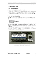
Open the front access door using a flathead screwdriver to
turn the lock.
2.
Remove the lower access panel or protection cover.
3.
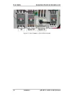
Turn off
ALL
the circuit breaker switches:
•
Rectifier CB
•
Static Switch Bypass CB
•
Output CB
•
Battery CB
•
Maintenance Bypass CB (should already be
off)
4.
Ensure that the circuit breakers for all lines from the electrical supply
board are OFF. Check for zero voltage on all lines before continuing.
5.
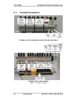
Connect one electrical supply cables to the Rectifier AC Input.
Connect a separate electrical supply cable and Bypass AC Input
terminals of the UPS. Be sure correct phase sequence is followed.
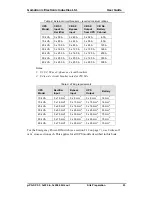
Use the proper wire grades, as listed in Table 9 on page 43.
Note: It is critically important that the Rectifier AC Input and Bypass AC Input
are fed from different points of the electrical supply board, each with its own
separate circuit breaker. For required circuit breaker capacities, see Table 8 on
page 43.
6.
Connect a cable to the UPS’s AC Output terminal. Connect the other
end of the cable to the distribution board or to a load device or a
dummy load, according to your location’s requirements.
7.
Connect a ground cable to the UPS ground terminal or ground bus
8.
An Emergency Power-Off switch can be installed to enable
immediate shutdown of the UPS. Use of a large, external,
mushroom-type NC (normally closed) pushbutton rated at 25VCD,
0.1A minimum, is recommended. Connect the Emergency Power-Off
switch to the Emergency Power-Off terminals using a 2-wire cable
with each wire having a cross-section of 1 mm
2.
Summary of Contents for PS-SP Series
Page 1: ......

