background image

Troubleshooting 

ROBO-8716VG2A User’s Manual 


5-4 

 
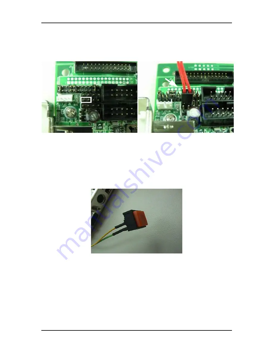
Step 3: Connect TOGGLE SWITCH (J10) connector on ROBO-8716VG2A (Figure 5-6), 

which is used to power on ATX Power Supply. Generally, the TOGGLE 
SWITCH is located on the chassis of front panel. 


Figure  5-6 


Step 6: The figure below is the TOGGLE SWITCH, which is used to switch the ATX 

Power on/off for SBC. Usually the TOGGLE SWITCH is located on the 
chassis front panel. Pressing the switch button once will turn power on, and 
press again to turn it off. (Figure 5-7) 


Figure  5-7 


Summary of Contents for ROBO-8716VG2A

Page 1: ...ROBO 8716VG2A Single Board Computer User s Manual P N B8980250 Version 1 1 Copyright Portwell Inc 2007 All rights reserved All other brand names are registered trademarks of their respective owners...

Page 2: ...4 On board AC 97 Audio Device 3 6 3 4 Clear CMOS Operation 3 7 3 5 WDT Function 3 7 3 6 GPIO 3 9 Chapter 4 BIOS Setup Information 4 1 4 1 Entering Setup 4 1 4 2 Main Menu 4 2 4 3 Standard CMOS Setup...

Page 3: ...tch Dog Timer function Chapter 4 BIOS Setup Information Specifies the meaning of each setup parameters how to get advanced BIOS performance and update new BIOS In addition POST checkpoint list will gi...

Page 4: ...romagnetic Compatibility Directive 89 336 EEC The equipment was evaluated and passed the test the following standards were applied EMC EN 55022 1994 A1 1995 Class A EN 50082 2 1991 EN 61000 4 2 1995 E...

Page 5: ...e pulled out from socket when taking cooler off This action may damage processor socket which will cause poor contact between CPU socket Handling SBC Caution Do not just hold any single side of the SB...

Page 6: ...ansion bus without extra bridge Another excellent feature of it is dual SATA port SATA interface definitely the one that will replace traditional IDE interface from the trend of chipset and storage de...

Page 7: ...ing please contact your vendor and keep all packing materials for future replacement and maintenance 1 3 Product Specification Main Features Intel 845GV based PICMG 1 0 SBC with VGA LAN Audio Support...

Page 8: ...port DMI PnP Green function and ACPI ACPI support suspend to RAM USB wake up On Board I O PCI IDE Interface Support two enhanced IDE channel up to four HDDs with PIO mode 4 Ultra DMA 33 66 100 model t...

Page 9: ...ort CPU voltage temperature and FAN monitoring Watchdog Timer Support WDT function through software programming Software programmable time out internal setting Generate system reset Real Time Clock Ca...

Page 10: ...k status on RJ45 jack Expansion Interface ROBO 8716VG2A supports one 32 bit 33MHz PCI bus and one 64 bit 66MHz PCI X bus via PICMG 1 2 backplane Physical and Environmental requirements Outline Dimensi...

Page 11: ...ile Celeron processor DDR SDRAM 2D 3D graphic display and 6300ESB I O controller hub supports one PCI one PCI X interface APM ACPI compliant power management two UARTs four USB ports SMBus communicati...

Page 12: ...System Overview ROBO 8716VG2A User s Manual 1 7 ROBO 8716VG2A System Block Diagram...

Page 13: ...ition The default settings shipped from factory are marked with a star 2 1 Jumper Setting 1 2 1 2 1 1 2 1 2 1 2 1 2 1 2 1 J2 J5 J16 J15 J14 J13 J8 J1 J4 J20 JP3 J19 J18 1 1 1 1 1 1 1 1 1 1 1 1 1 J17 J...

Page 14: ...mputer Connector Function List Connector Description Remark J1 Parallel Port Connector J2 J5 IDE1 IDE2 Interface Connector J3 4P Header for CPU 12V Power J4 FDC Interface Connector J6 HDD LED Header J...

Page 15: ...Flash Socket on IDE1 Master Pin Assignments of Connectors J3 4P Header for CPU 12V Power PIN No Signal Description 1 GND 2 GND 3 12V 4 12V J28 PS 2 Keyboard Mouse Connector PIN No Signal Description 1...

Page 16: ...10 Data 11 11 Data 3 12 Data 12 13 Data 2 14 Data 13 15 Data 1 16 Data 14 17 Data 0 18 Data 15 19 Ground 20 N C 21 DMA REQ 22 Ground 23 IOW 24 Ground 25 IOR 26 Ground 27 IOCHRDY 28 Pull down 29 DMA A...

Page 17: ...22 Data 1 23 Data 2 24 NC 25 NC 26 NC 27 Data 11 28 Data 12 29 Data 13 30 Data 14 31 Data 15 32 SDCS 3 33 Ground 34 IOR 35 IOW 36 WE 37 INT 38 5V 39 Ground 40 NC 41 RESET 42 IORDY 43 NC 44 REQ 45 IDE...

Page 18: ...d Clock 2 Keyboard Data 3 NC 4 GND 5 5V J17 J29 J35 Fan Header PIN No Signal Description 1 GND 2 12V 3 Speed Sense to SIO J10 Power On Header PIN No Signal Description 1 5VSB 2 Power On J11 Reset Head...

Page 19: ...LED 4 Key lock 5 GND J6 HDD LED Header PIN No Signal Description 1 5V 2 IDEACT J19 IR Header PIN No Signal Description 1 5V 2 GND 3 IRRX 4 GND 5 IRTX 6 NC J20 External SMBus Header PIN No Signal Desc...

Page 20: ...eld GND 5 D0 6 D1 7 Shield GND 8 D1 9 Shield GND 10 VCC J23 J24 Serial ATA 1 and 2 PIN No Signal Description 1 4 7 GND 2 TXP 3 TXN 5 RXN 6 RXP J26 27 Ethernet RJ 45 Interface Connector PIN No Signal D...

Page 21: ...AGND 3 LINE IN Left 4 AGND 5 LINE IN Right 6 AGND 7 LINE OUT Left 8 AGND 9 LINE OUT Right J30 CD IN Header PIN No Signal Description 1 CD L 2 CDGND 3 CDGND 4 CD R J34 D SUB 15 VGA Connector PIN No Si...

Page 22: ...22 Ground 10 Acknowledge 23 Ground 11 Busy 24 Ground 12 Paper Empty 25 Ground 13 Printer Select 26 N C J4 FDC Interface Connector PIN No Signal Description PIN No Signal Description 1 GND 2 Density Se...

Page 23: ...programming 3 1 Pentium 4 Processor Installing Socket 478 CPU 1 Lift the handling lever of CPU socket outwards and upwards to the other end 2 Align the processor pins with pinholes on the socket Make...

Page 24: ...Signal Description 1 GND 2 GND 3 12V 4 12V Removing CPU 1 Unlock the cooling fan first 2 Lift the lever of CPU socket outwards and upwards to the other end 3 Carefully lifts up the existing CPU to rem...

Page 25: ...ability don t change any of DRAM parameters in BIOS setup to upgrade your system performance without acquiring technical information Memory frequency CPU FSB synchronization ROBO 8716VG2A support diff...

Page 26: ...VG2A is a new chipset that a few old operating systems might not be able to recognize To overcome this compatibility issue for Windows Operating Systems such as Windows 98SE 2000 XP please install its...

Page 27: ...f multimedia hardware With no additional video adaptor this onboard video will usually be the system display output By adjusting the BIOS setting to disable on board VGA an add on PCI VGA card can tak...

Page 28: ...as a quick reference guide Operation of Ethernet Port 88E8001 Name of LED ON OFF Green LAN Linked Active LED Linked Active Blinking LAN speed LED All Off N A 10 Mbps Green Speed LED 100 Mbps N A Amber...

Page 29: ...hrough dynamic software programming The WDT starts counting when it is activated It sends out a signal to system reset or to non maskable interrupt NMI when time out interval ends To prevent the time...

Page 30: ...0x002F inp 0x002F 0xEF Select Logic Device 8 outp 0x002E 0x07 outp 0x002F 0x08 Active Logic Device 8 outp 0x002E 0x30 outp 0x002F 0x01 Select Count Mode outp 0x002E 0xF5 outp 0x002F inp 0x002F 0xF7 Co...

Page 31: ...100mA J8 8 Bit GPIO Header PIN No Signal Description 1 General Purpose I O Port 1 GPIO14 2 General Purpose I O Port 2 GPIO15 3 General Purpose I O Port 3 GPIO16 4 General Purpose I O Port 4 GPIO17 5...

Page 32: ...PIO port 1 Bit5 vs GPIO port 2 Bit6 vs GPIO port 3 Bit7 vs GPIO port 4 Value of Inversion Register Only high nibble is available for this function When set to a 1 the incoming outgoing port value is i...

Page 33: ...er s Manual 3 11 Notes 1 All the Buffered Digital Outputs are open drain amplified form corresponding GPIO ports 2 Some other functions may occupy the lower nibble of the registers Altering any conten...

Page 34: ...r reboot the computer When the message Hit DEL if you want to run SETUP appears press Del key immediately to enter BIOS setup program If the message disappears before you respond but you still wish to...

Page 35: ...Phoenix AwardBIOS CMOS Setup Utility f Standard CMOS Features f Advanced BIOS Features f Advanced Chipset Features f Integrated Peripherals f Power Management Setup f PnP PCI Configurations f PC Heal...

Page 36: ...irus Protection Status Phoenix AwardBIOS CMOS Setup Utility Standard CMOS Features Item Help Date mm dd yy Wed May 11 2005 Time hh mm ss 11 29 50 f IDE Channel 0 Master Maxtor 91021U2 f IDE Channel 0...

Page 37: ...re in its sub menu Press Enter to enter the next page for detail hard drive settings STAT0 Master Options are in its sub menu Press Enter to enter the next page for detail hard drive settings STAT1 Ma...

Page 38: ...ove Enter Select PU PD Value F10 Save ESC Exit F1 General Help F5 Previous Values F6 Fail Safe Defaults F7 Optimized Defaults Menu Selections Item Options Description IDE HDD Auto detection Press Ente...

Page 39: ...heads Precomp Min 0 Max 65535 Warning Setting a value of 65535 means no hard disk Landing zone Min 0 Max 65535 Sector Min 0 Max 255 Number of sectors per track Phoenix AwardBIOS CMOS Setup Utility SA...

Page 40: ...ollowing options are selectable only if the SATA 0 Master item is set to Manual Capacity Auto Display your disk drive size Disk drive capacity Approximated Note that this size is usually slightly grea...

Page 41: ...nabled Hyper Threading Technology Enabled Quick Power On Self Test Enabled First Boot Device Hard Disk Second Boot Device CD ROM Third Boot Device ZIP100 Boot Other Device Enabled Swap Floppy Drive Di...

Page 42: ...7 Optimized Defaults Limit CPUID Maxval Set Limit CPUID MaxVal to 3 Should Be Disabled for WinXP Enabled For OS Windows NT4 0 Install Disabled For OS Windows XP Install Phoenix AwardBIOS CMOS Setup Ut...

Page 43: ...ates automatically when the system boots up causing a warning message to appear when anything attempts to access the boot sector or hard disk partition table Disabled No warning message will appear wh...

Page 44: ...t Up Floppy Seek Enabled tests floppy drives to determine whether they have 40 or 80 tracks The choice Enabled Disabled Boot Up NumLock Status Select power on state for NumLock The choice Off On Gate...

Page 45: ...t boot and access to Setup will be denied if the correct password is not entered at the prompt Setup The system will boot but access to Setup will be denied if the correct password is not entered at t...

Page 46: ...em Help DRAM Timing Selectable By SPD X CAS Latency Time 2 5 X Active to Precharge Delay 7 X DRAM RAS to CAS Delay 3 X DRAM RAS Precharge 3 Memory Frequency For Auto System BIOS Cacheable Enabled Vide...

Page 47: ...The choice 7 6 and 5 DRAM RAS to CAS Delay This option controls the number of SCLKs SDRAM Clock from a row activate command to a read or write command If your system installs good quality of SDRAM yo...

Page 48: ...nabled Disabled Memory Hole At 15 16M In order to improve performance certain space in memory is reserved for ISA cards This memory must be mapped into the memory space below 16MB The choice Enabled D...

Page 49: ...aults Phoenix AwardBIOS CMOS Setup Utility OnChip IDE Device Item Help IDE DMA transfer access Enabled On Chip Primary PCI IDE Enabled IDE Primary Master PIO Auto IDE Primary Slave PIO Auto IDE Primar...

Page 50: ...ode 0 Mode 1 Mode 2 Mode 3 and Mode 4 IDE Primary Secondary Master Slave UDMA Ultra DMA 33 66 100 implementation is possible only if your IDE hard drive supports it and the operating environment inclu...

Page 51: ...bled Disabled USB 2 0 Controller This entry is for disable enable EHCI controller only This BIOS itself may may not have high speed USB support built in the support will be automatically turn on when...

Page 52: ...Select PU PD Value F10 Save ESC Exit F1 General Help F5 Previous Values F6 Fail Safe Defaults F7 Optimized Defaults Power On Function This item allows you to select different power on scheme using AT...

Page 53: ...t The choice Disabled 378 IRQ7 278 IRQ5 and 3BC IRQ7 Parallel Port Mode There are four different modes for the onboard parallel port SPP Switch to SPP mode EPP Switch to EPP mode ECP Switch to ECP mod...

Page 54: ...This item is to configure Infrared transmission rate Four options are available Hi Hi High rate for receiving High rate for transmitting Hi Lo High rate for receiving Low rate for transmitting Lo Hi L...

Page 55: ...Enabled Power Management User Define Video Off Method DPMS Video Off In Suspend Yes Suspend Type Stop Grant Suspend Mode Disabled HDD Power Down Disabled Soft Off by PWR BTTN Instant Off Intruder Dete...

Page 56: ...t Suspend Mode 1 Min and HDD Power Down 1 Min User Defined Allow you to set each mode individually When not disabled Suspend Mode ranges from 1 min to 1 Hour and HDD Power Down ranges from 1 Min to 15...

Page 57: ...8 Min 9 Min 10 Min 11 Min 12 Min 13 Min 14 Min 15 Min Soft Off by PWR BTTN This item allows users to set the time to remove the power after the power button is pressed The choice Instant Off Delay 4 S...

Page 58: ...nabled this item could allow users to configure the time parameter of the timing dateline on which to power on the system The choice hh 0 23 mm 0 59 ss 0 59 Primary Secondary IDE 0 1 This item is to c...

Page 59: ...enu Level f Default is disabled Select Enabled to reset Extended System Configuration Data ESCD when you exit Setup if you have installed a new add on and the system reconfiguration has caused such a...

Page 60: ...r devices compliant with the original PC AT bus specification PCI ISA PnP for devices compliant with the plug and play standard whether designed for PCI or ISA bus architecture IRQ 3 IRQ 4 IRQ 5 IRQ 7...

Page 61: ...VSB V 4 96 V Menu Level f Move Enter Select PU PD Value F10 Save ESC Exit F1 General Help F5 Previous Values F6 Fail Safe Defaults F7 Optimized Defaults CPU Throttle Temperature This item allows you t...

Page 62: ...e Defaults When you press Enter on this item you get a confirmation dialog box with a message similar to Load Fail Safe Defaults Y N N Pressing Y loads the BIOS default values for the most stable mini...

Page 63: ...o press Esc to abort the selection and not enter a password To disable a password just press Enter when you are prompted to enter the password A message will confirm the password will be disabled Once...

Page 64: ...ays on after you turn your system off The next time you boot your computer the BIOS configures your system according to the Setup selections stored in CMOS After saving the values the system is restar...

Page 65: ...on issues in terms of backplane setup BIOS setting and OS diagnostics 5 1 Quick installation Guide Backplane ROBO 8716VG2A is a full sized Single Board Computer and therefore is only able to run on PI...

Page 66: ...fication of the PCI Device Golden Fingers could meet our design of PCI PCI X architecture for ROBO 8716VG2A The below picture shows the PCI Slot Pin definition Figure 5 2 5 3 The 5V 64 bit PCI slots F...

Page 67: ...lowing instruction Step1 Connect 20 pin power cable of the ATX POWER with ATX POWER CONNECTOR 20 pin on the backplane Figure 5 4 Figure 5 4 Step2 ROBO 8716VG2A requires power drawing through golden fi...

Page 68: ...Supply Generally the TOGGLE SWITCH is located on the chassis of front panel Figure 5 6 Step 6 The figure below is the TOGGLE SWITCH which is used to switch the ATX Power on off for SBC Usually the TO...

Page 69: ...isplay Card error Please check Monitor connector whether it inserts properly Beep rapidly Power error warning Please check Power mode setting Symptom There is neither no beeps nor screen output Soluti...

Page 70: ...advance On the contrary leave the jumper JP1 open for using the Intel Pentium 4 Processor with Hyper Threading Technology and Intel Pentium 4 Celeron Processor Q What is Serial ATA and how to use it e...

Page 71: ...hardware won t be recognized To enable SATA function please see as following Q Can I build Raid system on SATA bus with ROBO 8716VG2A A No it cannot It is because ROBO 8716 s south bridge is ICH5 HR w...

Page 72: ...on the system Why A There are thousands of different reasons to get this power on failure 1 Check ROBO 8716VG2A jumper JP1 Otherwise incorrect power setting will not allow you to power on the system 2...

Page 73: ...on successfully you must install ATA 66 100 driver then the function can be active Q After inserting Compact Flash why doesn t it work at all A Compact flash is occupied with the master device of IDE...

Page 74: ...k to the initial factory configuration It is recommended to do this so you can be sure the system is running with the BIOS setting that Portwell has highly endorsed As a matter of fact users can load...

Page 75: ...lel Port IRQ 8 CMOS Clock IRQ 9 Display Controller IRQ 9 USB 1 0 1 1 EHCI Controller IRQ 9 ACPI Controller Shareable IRQ 10 Ethernet Controller Shareable IRQ 10 USB 2 0 EHCI Controller Shareable IRQ 1...

Page 76: ...e Device Description 0000 003F 1K Interrupt Area 0040 004F 0 3K BIOS Data Area 0050 006F 0 5K System Data 0070 03E1 13K DOS 03E2 0BB9 31K Program Area 0BBA 9F3F 590K Available Conventional memory ends...

Page 77: ...RV System Timer IRQ 1 SMARTDRV Keyboard Event IRQ 2 Unassigned Usable IRQ IRQ 3 System ROM COM 2 IRQ 4 System ROM COM 1 IRQ 5 Unassigned Usable IRQ IRQ 6 System ROM Diskette Event IRQ 7 Unassigned Usa...

Reviews: