3-4
3 First Steps
3.3
Control Elements, Displays and Connections
3.3.1
PSV-F-500-HM Front-End
Front view
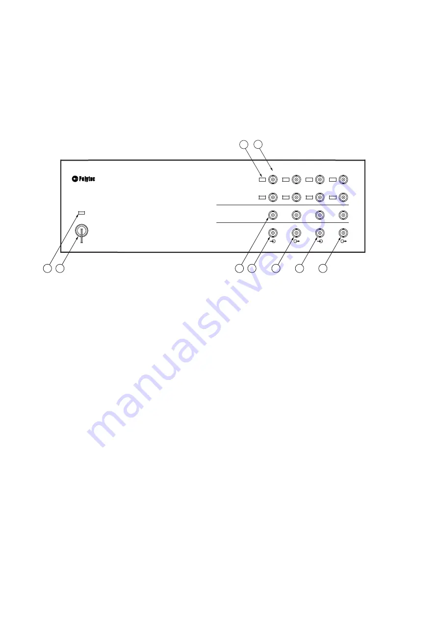
The connections on the front are only used for the operation as an H system
(exception: AUX IN and AUX OUT). The front view of the front-end is shown in
the following figure.
Figure 3.1:
Front view of the front-end
1
IEPE 1
to
IEPE 8
L
ED
s
L
ED
is lit up: IEPE power supply for the corresponding reference input (REF 1 to
REF 8) activated in the software
2
REF 1
analog input (BNC jack)
Analog voltage input for the reference signal. You can also connect a sensor
equipped with an integrated amplifier to this input, according to the IEPE concept,
also known as ICP® (4 mA / 24 V). Activating or deactivating the IEPE power
supply is described in your software manual.
REF 2
to
REF 8
analog inputs (BNC jacks)
There are up to seven additional analog voltage inputs are available for reference
signals.
3
SYNC
TTL output (BNC jack)
TTL output for the SYNC signal of the function generator
4
TRIG IN
TTL input (BNC jack)
TTL input for an external trigger signal
5
AUX OUT
TTL output (BNC jack)
TTL output for special applications (programmable via Visual Basic® Engine)
6
AUX IN
TTL input (BNC jack)
TTL input for special applications and also to connect the PSV-A-430 acoustic
gate unit (programmable via Visual Basic® Engine)
9
8
6
5
4
3
7
1
2
I
EPE
I
EPE
I
EPE
I
EPE
I
EPE
I
EPE
I
EPE
PSV-5
00
V
I
BROMETER
FRONT
-
END
O
I
POWER
ANALOG
I
N
GENERATOR
OUT
D
I
G
I
TAL
I
/O
AUX
I
N
TR
I
G
I
N
AUX
OUT
SYNC
S
I
GNAL
1
S
I
GNAL
2
S
I
GNAL
3
S
I
GNAL4
REF5
REF6
REF8
REF7
REF
1
REF
2
REF
3
REF4
I
EPE
Summary of Contents for PSV-500
Page 10: ...1 6 1 Safety Information...
Page 14: ...2 4 2 Introduction...
Page 50: ...4 8 4 Making Measurements...
Page 104: ...C 2 C Declaration of Conformity...


