

5.34
BODY / STEERING / SUSPENSION
9924125 - 2013
RANGER
RZR / RZR S / RZR 4 Service Manual
© Copyright 2012 Polaris Sales Inc.
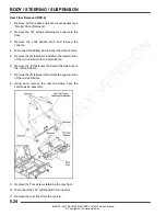
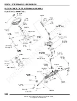
FRONT A-ARMS
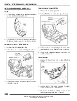
Removal / Replacement
The following procedure details upper and lower A-arm
removal and replacement on one side of the vehicle.
1.
Elevate and safely support the front of the vehicle and
remove the front wheel.
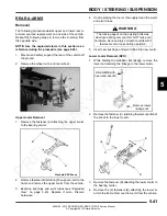
2.
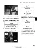
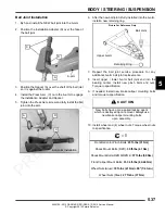
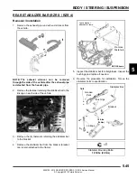
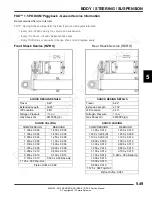
Remove lower shock fastener (A) from upper A-arm.
3.
Remove upper ball joint pinch bolt (B) from bearing
carrier.
4.
Using a soft face hammer, tap on bearing carrier to
loosen the upper A-arm ball joint end while lifting
upward on the upper A-arm. Completely remove the
ball joint end from the bearing carrier.
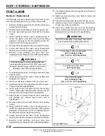
5.
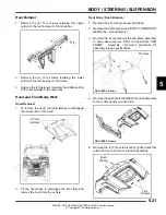
Remove the front bumper to allow A-arm bolt removal.
6.
Loosen and remove the upper A-arm through-bolt
fastener (C) and remove upper A-arm from vehicle.
7.
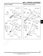
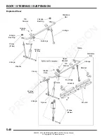
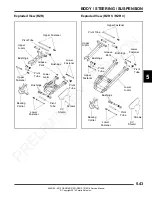
Examine A-arm bushings and pivot tube (see
“Exploded View”). Replace if worn. Discard hardware.
8.
If not replacing the A-arm, thoroughly clean the A-arm
and pivot tube.
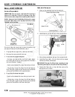
9.
Install new ball joint into A-arm. Refer to “Ball Joint
Replacement” section.
10. Insert new bushings and pivot tube into new A-arm.
11. Install new upper A-arm assembly onto vehicle frame.
Torque new bolt to specification.
12. Insert upper A-arm ball joint end into the bearing
carrier. Install upper ball joint pinch bolt (B) into the
bearing carrier and torque bolt to specification.
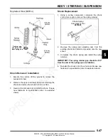
13. Attach shock to A-arm with spacer (D) or washer (G)
and fastener (A). Torque lower shock bolt to
specification.
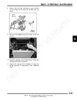
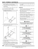
14. Remove lower ball joint pinch bolt (E) from bearing
carrier.
15. Using a soft face hammer, tap on bearing carrier to
loosen the lower A-arm ball joint end while pushing
downward on the lower A-arm. Completely remove
the ball joint end from the bearing carrier.
16. Loosen and remove the lower A-arm through-bolt
fastener (F) and remove lower A-arm from the vehicle.
17. Examine A-arm bushings and pivot tube (see
“Exploded View”). Replace if worn. Discard hardware.
18. If not replacing the A-arm, thoroughly clean the A-arm
and pivot tube.
19. Install new ball joint into A-arm. Refer to “Ball Joint
Service” section.
20. Insert new bushings and pivot tube into new A-arm.
21. Install new lower A-arm assembly onto vehicle frame.
Torque new bolt to specification.
22. Insert lower A-arm ball joint end into the bearing
carrier. Install lower ball joint pinch bolt (E) into the
bearing carrier and torque bolt to specification.
WARNING
The locking agent on the existing bolts was
destroyed during removal. DO NOT reuse old
hardware. Serious injury or death could result if
fasteners come loose during operation.
WARNING
Upon A-arm installation completion, test vehicle
at low speeds before putting into service.
=
T
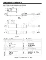
Front Upper / Lower A-arm Bolts:
RZR:
37 ft-lbs (50 Nm)
RZR S / RZR 4:
40 ft-lbs (54 Nm)
=
T
Front Ball Joint Pinch Bolts:
23 ft-lbs (31 Nm)
=
T
Shock Mounting Bolts:
RZR:
30 ft-lbs (41 Nm)
RZR S / RZR 4:
37 ft-lbs (50 Nm)
A
B
C
D
E
F
Standard RZR Shown
A
G
PRELIMINARY
VERSION
Summary of Contents for 2013 RANGER RZR
Page 417: ...2013 RANGER RZR 800...
Page 418: ...2013 RANGER RZR 800...
Page 419: ...2013 RANGER RZR 800 EPS...
Page 420: ...2013 RANGER RZR 800 EPS...
Page 421: ...2013 RANGER RZR S 800...
Page 422: ...2013 RANGER RZR S 800...
Page 423: ...2013 RANGER RZR S 800 INT L...
Page 424: ...2013 RANGER RZR S 800 INT L...
Page 425: ...2013 RANGER RZR 4 800...
Page 426: ...2013 RANGER RZR 4 800...
Page 427: ...2013 RANGER RZR 4 800 EPS...
Page 428: ...2013 RANGER RZR 4 800 EPS...


