


Flex-View Event Presentation Switching Solution
User Manual
8 U3 Event Controller
www.pixelhue.com
121
Blank buttons and OLED labels: Six blank function buttons are reserved for your
future use, and the OLED labels display the function name.
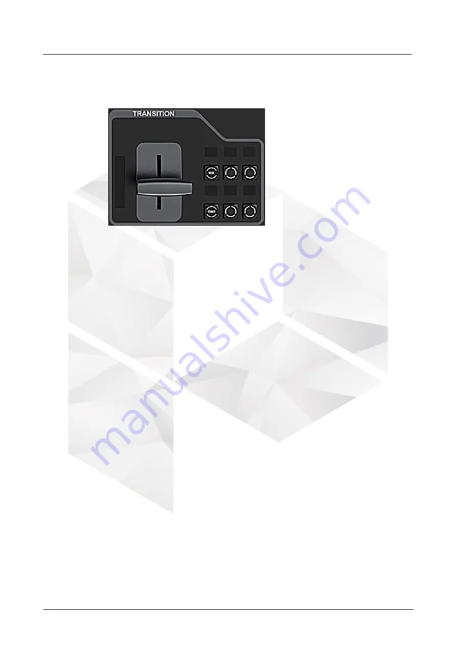
8.4.1.7 TRANSITION
A manual transition T-bar is provided on this event controller. It locates at the
lower right of the controller for user convenience.
The T-bar transitions from 0 to 100% and has an LED bar indicating the transition
progress.
LED bar: Its status corresponds to the T-Bar progress.
T-Bar: Control the transition speed manually.
MIX: Turn on or turn off the fade effect.
TIME: Set the transition effect duration. Press the button to increase the duration
by 0.1s. The OLED label above the button displays the effect duration.
Blank buttons and OLED labels: Four blank function buttons are reserved for your
future use, and the OLED labels display the function name.
8.4.2 Mouse and Keyboard
1.
Connect the mouse and keyboard to the USB ports located at the U3 side or
rear panel.
2.
Perform necessary operations by using the mouse and keyboard.
8.4.3 Touchscreens
Two touchscreens allow you to operate the device via simple finger touch operations.
8.5 Connections
8.5.1 Connecting with F8/F4
Method I
Connect either of the Ethernet ports on the rear panel of the U3 event controller
to the Ethernet port on the control card of the F8/F4 for device control.
Method II
Connect both the Ethernet port on the rear panel of the U3 event controller and
the Ethernet port on the control card of the F8/F4 to the router.


