LAMAR MODEL NO. B-00392-1 VOLTAGE REGULATOR OPERATION
1. The Lamar no. B00392-1 voltage regulator delivers a pulse width modulated field control output, as
required, to maintain the alternator output voltage.
2. An overvoltage protection is incorporated, which latches off regulator output following an overvoltage
event.
3. The regulator is protected against damage due to output (field) short to ground. A short will latch off
the output until reset.
4. Momentarily turn OFF 14 Volt power supply to reset latch off caused by either an overvoltage or
shorted output.
5. Field pulse rise and fall times are slowed to be more that 50 microseconds.
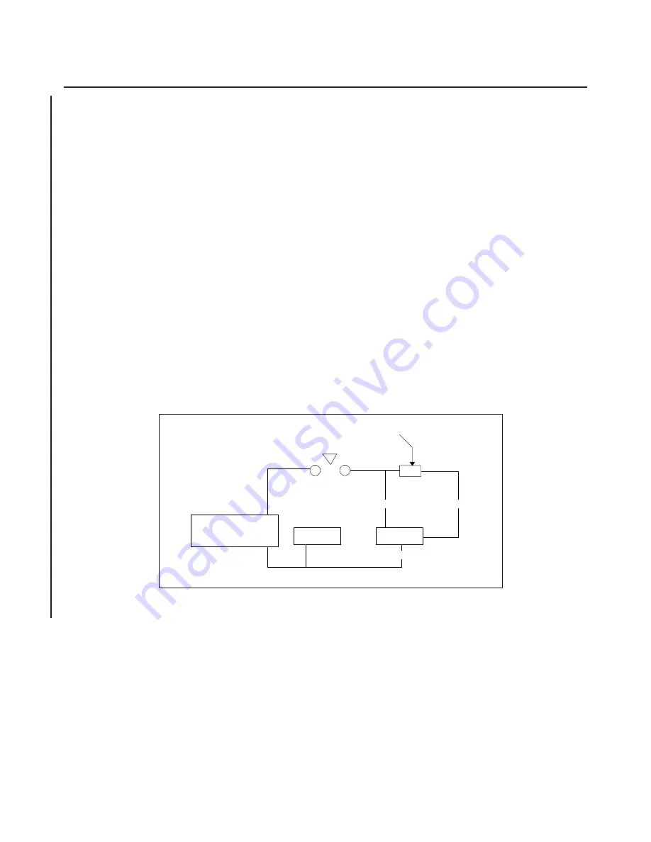
6. Refer to Figure 24-8 to check overvoltage operation. Temporary indicator will be activated when
overvoltage circuit locks out. (See CAUTION.)
7. In an operating system (2 units with equalizer connection), an excess current in one shunt, due to an
overvoltage condition in that side, will cause the opposite side overvoltage sensing to be desensitized.
The side causing the overvoltage will be selectively tripped. Excess shunt current will then fall to
zero, which permits the normal side overvoltage sensitivity to restore to its calibrated value.
8. Except for the equalizer connection, the left and right alternator systems are independent of each other.
The equalizer connection will NOT cause a failure in one system to disable the other normal operating
system.
9. The equalizer circuit may be faulted to either ground or the bus with no damage to either system.
Balancing action and selectivity of the overvoltage trip protection will be lost. If the equalizer faulted
to the bus, system voltage will increase to the limit of balancing circuit control authority (less than 1
Volt). The overvoltage operating point of both systems will be elevated to the value provided for
selective trip action (approximately 2 Volts above the normal overvoltage trip calibration point).
Figure 24-8. Lamar 00392-1 Regulator Overvoltage Test Method
ADJUSTING VOLTAGE REGULATOR UNIT. (LAMAR MODEL NO. B-00392-1)
The only adjustment necessary to maintain the alternator system is the adjustment of the voltage control on
the voltage control unit. A voltage of 14 volts dc is automatically maintained. All other adjustments are made
at the time of installation and need not be reset.
— CAUTION —
IN-AIRCRAFT TESTING WITH ALTERNATOR RUNNING IS NOT
RECOMMENDED. DO NOT BYPASS REGULATOR BUS TO FIELD AS A
MEANS OF CHECKING ALTERNATOR WITH ALTERNATOR RUNNING.
PIPER AIRCRAFT
PA-44-180/180T
AIRPLANE MAINTENANCE MANUAL
24 -23-10
Page 24-22
Revised: June 20, 1995
1J10
PURE D. C.
REGULATED
SUPPLY
PRECISION
V/M
B-00392-1
REGULATOR
IND.
RED
BLUE
+
-
PTT
BLACK
TEMPORARY INDICATOR. USE A 28 V
B U L B O R A R E L A Y . N O O T H E R
CONNECTIONS ON THE BLUE CIRCUIT
DURING THE TEST PROCEDURE
Summary of Contents for SEMINOLE PA-44-180
Page 38: ...CHAPTER DIMENSIONS AND AREAS 1B14...
Page 49: ...CHAPTER LIFTING AND SHORING 1C1...
Page 53: ...CHAPTER LEVELING AND WEIGHING 1C5...
Page 58: ...CHAPTER TOWING AND TAXIING 1C10...
Page 62: ...CHAPTER PARKING AND MOORING 1C14...
Page 65: ...CHAPTER REQUIRED PLACARDS 1C17...
Page 70: ...CHAPTER SERVICING 1C22...
Page 98: ...CHAPTER STANDARD PRACTICES AIRFRAME 1E2...
Page 108: ...CHAPTER ENVIRONMENTAL SYSTEM 1E12...
Page 189: ...CHAPTER AUTOFLIGHT 1H21...
Page 192: ...CHAPTER COMMUNICATIONS 1H24...
Page 202: ...CHAPTER ELECTRICAL POWER 1I10...
Page 228: ...CHAPTER EQUIPMENT FURNISHINGS 1J12...
Page 233: ...CHAPTER FIRE PROTECTION 1J17...
Page 238: ...CHAPTER FLIGHT CONTROLS 1J24...
Page 304: ...2A18 CHAPTER FUEL...
Page 325: ...2B17 CHAPTER HYDRAULIC POWER...
Page 357: ...2D1 CHAPTER ICE AND RAIN PROTECTION...
Page 414: ...CHAPTER LANDING GEAR 2F13...
Page 479: ...2I6 CHAPTER LIGHTS...
Page 488: ...2I16 CHAPTER NAVIGATION AND PITOT STATIC...
Page 503: ...2J7 CHAPTER OXYGEN...
Page 524: ...2K6 CHAPTER VACUUM...
Page 535: ...2K19 CHAPTER ELECTRICAL ELECTRONIC PANELS AND MULTIPURPOSE PARTS...
Page 546: ...INTENTIONALLY LEFT BLANK PA 44 180 180T AIRPLANE MAINTENANCE MANUAL 2L6 PIPER AIRCRAFT...
Page 547: ...2L7 CHAPTER STRUCTURES...
Page 582: ...CHAPTER DOORS 3A18...
Page 593: ...CHAPTER STABILIZERS 3B8...
Page 604: ...CHAPTER WINDOWS 3B22...
Page 611: ...CHAPTER WINGS 3C10...
Page 624: ...CHAPTER PROPELLER 3D1...
Page 643: ...CHAPTER POWER PLANT 3D21...
Page 667: ...CHAPTER ENGINE FUEL SYSTEM 3F1...
Page 681: ...CHAPTER IGNITION 3F16...
Page 712: ...CHAPTER ENGINE INDICATING 3H1...
Page 730: ...CHAPTER EXHAUST 3H19...
Page 734: ...CHAPTER OIL 3I1...
Page 743: ...CHAPTER STARTING 3I11...
Page 755: ...CHAPTER TURBINES 3J1...


