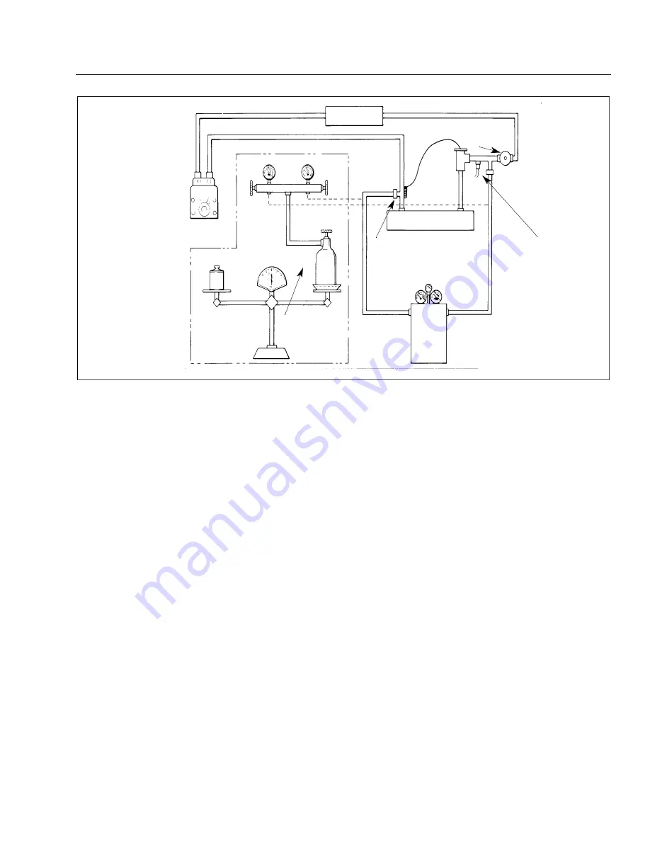
Figure 21-30. Charging Hookup
2. Place the refrigerant container on a scale to observe the amount of refrigerant entering the system. Open
the high pressure valve and add as much refrigerant as possible.
3. Close the high pressure valve. start the engine and operate it at 900 to 1000 RPM.
4. Operate the air conditioner and set controls to maximum cooling.
5. Open the low pressure valve and complete charging the system.
6. Close the low pressure valve after two pounds of refrigerant has been added to the system.
7. With the system still operating, observe the sight glass in the top of the receiver-dehydrator by removing
the plastic plug.
8. The sight glass should be clear of any bubbles or foam. If bubbles or foam are seen passing through the
sight glass. it is an indication of a low refrigerant charge in the system and more refrigerant is required.
This check should be made with OAT of 70° F or higher and with the air conditioner opening.
9. If more refrigerant must be added to the system, open the low pressure valve and increase engine speed to
2000 RPM and observe the sight glass. After the sight glass has cleared, close the low pressure valve and
observe the pressure gauges. At 1000 RPM the gauge pressure should be 15 to 20 psi on the low side and
150 to 200 on the high side.
— Note —
Suspect leaks or an inaccurate scale if two pounds of refrigerant does not fill the
system.
PRESSURE
SWITCH
SCHRADER
VALVE FITTING
CHARGING
STAND
REFRIGERANT
R12
CAPILLARY
COIL
EXPANSION
VALVE
RECEIVER
DEHYDRATOR
SIGHT GLASS
CONTAINER OF
WARM WATER
(125°F)
THIS END OF HOSE
MUST HAVE DEVICE
TO DEPRESS
SCHRADER VALVE
OPTIONAL METHOD
PREFERRED
METHOD
HP
SCALE
LP
CONDENSER
DISCHARGE LINE
SUCTION LINE
COMPRESSOR
EVAPORATOR
PA - 4 4 - 1 8 0 / 1 8 0 T
AIRPLANE MAINTENANCE MANUAL
2 1 - 5 2 - 0 9
Page 21-66
Revised: May 15, 1989
1H9
PIPER AIRCRAFT
Summary of Contents for SEMINOLE PA-44-180
Page 38: ...CHAPTER DIMENSIONS AND AREAS 1B14...
Page 49: ...CHAPTER LIFTING AND SHORING 1C1...
Page 53: ...CHAPTER LEVELING AND WEIGHING 1C5...
Page 58: ...CHAPTER TOWING AND TAXIING 1C10...
Page 62: ...CHAPTER PARKING AND MOORING 1C14...
Page 65: ...CHAPTER REQUIRED PLACARDS 1C17...
Page 70: ...CHAPTER SERVICING 1C22...
Page 98: ...CHAPTER STANDARD PRACTICES AIRFRAME 1E2...
Page 108: ...CHAPTER ENVIRONMENTAL SYSTEM 1E12...
Page 189: ...CHAPTER AUTOFLIGHT 1H21...
Page 192: ...CHAPTER COMMUNICATIONS 1H24...
Page 202: ...CHAPTER ELECTRICAL POWER 1I10...
Page 228: ...CHAPTER EQUIPMENT FURNISHINGS 1J12...
Page 233: ...CHAPTER FIRE PROTECTION 1J17...
Page 238: ...CHAPTER FLIGHT CONTROLS 1J24...
Page 304: ...2A18 CHAPTER FUEL...
Page 325: ...2B17 CHAPTER HYDRAULIC POWER...
Page 357: ...2D1 CHAPTER ICE AND RAIN PROTECTION...
Page 414: ...CHAPTER LANDING GEAR 2F13...
Page 479: ...2I6 CHAPTER LIGHTS...
Page 488: ...2I16 CHAPTER NAVIGATION AND PITOT STATIC...
Page 503: ...2J7 CHAPTER OXYGEN...
Page 524: ...2K6 CHAPTER VACUUM...
Page 535: ...2K19 CHAPTER ELECTRICAL ELECTRONIC PANELS AND MULTIPURPOSE PARTS...
Page 546: ...INTENTIONALLY LEFT BLANK PA 44 180 180T AIRPLANE MAINTENANCE MANUAL 2L6 PIPER AIRCRAFT...
Page 547: ...2L7 CHAPTER STRUCTURES...
Page 582: ...CHAPTER DOORS 3A18...
Page 593: ...CHAPTER STABILIZERS 3B8...
Page 604: ...CHAPTER WINDOWS 3B22...
Page 611: ...CHAPTER WINGS 3C10...
Page 624: ...CHAPTER PROPELLER 3D1...
Page 643: ...CHAPTER POWER PLANT 3D21...
Page 667: ...CHAPTER ENGINE FUEL SYSTEM 3F1...
Page 681: ...CHAPTER IGNITION 3F16...
Page 712: ...CHAPTER ENGINE INDICATING 3H1...
Page 730: ...CHAPTER EXHAUST 3H19...
Page 734: ...CHAPTER OIL 3I1...
Page 743: ...CHAPTER STARTING 3I11...
Page 755: ...CHAPTER TURBINES 3J1...


