o. If the left wing is being removed, it will be necessary to disconnect pitot tube at the elbow located
within the cockpit at the wing butt line.
p. Arrange a suitable fuselage cradle and supports for both wings.
q. Remove the wing jacks.
r.
Remove the front and rear spar nuts, washers and bolts.
s.
Remove the eighteen main spar bolts.
t.
Slowly remove the wing being certain that all electrical leads, cables and lines are disconnected.
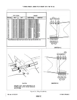
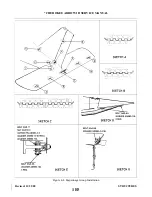
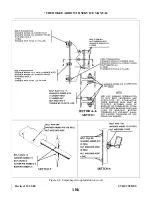
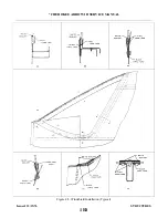
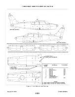
4-15. INSTALLATION OF WING. (Refer to Figure 4-2.)
a.
Ascertain that the fuselage is positioned solidly on a support cradle.
b. Place the wing in position for installation, with the spar end a few inches from the side of the fuselage
and set on trestles.
c.
Prepare the various lines, control cables, etc. for inserting into the wing or fuselage when the wing is
eased into place.
d. Slide the wing into position of the fuselage.
e.
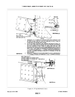
Install the eighteen main spar bolts in accordance with the bolt legend.
f.
Install the bolt, washers, and nut that attaches the front spar and fuselage fitting. A minimum of one
washer is required under the nut and head of bolt, then add washers as needed to leave a maximum of
one and on-half threads visible or a minimum of the bolt chamfer exposed.
g. Insert the number of washers required at the rear spar between the forward face of the wing fitting and
aft face of the fuselage fitting. The maximum number of washers allowed is two of AN960C-516. It is
also acceptable to have the faces of the fitting against each other. After the required washers are
inserted between the plates, install the bolt and check to insure that no threads are bearing on the
forward plate prior to installing the nut. Use the shortest bolt which will leave 0.580 of an inch
minimum from the fitting to the end of the bolt. Add washers, AN960-516, as required, (minimum of
one), to leave a maximum of one and one-half visible threads, or minimum of the bolt chamfer
exposed after the nut is torqued.
h. Torque the bolt heads on the upper spar cap and the nuts on the lower spar cap 360 to 390 inch pounds.
Be certain that the bolts, nuts and washers are installed in accordance with the bolt legend. (Figure 4-2.)
The forward spar attachment nut should be torqued 50 to 60 inch pounds. Torque the rear spar
attachment nut from 200 to 225 inch pounds.
i.
Install the wing jacks and the tail support to the tail skid with approximately 250 pounds of ballast on
the base of the tail support. Remove the fuselage cradle and wing supports.
j.
If the left wing was removed, it is necessary that the pitot tube be connected at the elbow located
within the cockpit at the wing butt line. Replace or install clamps where found necessary.
k. Connect the hydraulic brake line onto the fitting located within the cockpit at the leading edge of the
wing, and the landing gear hydraulic lines at the fittings within the fuselage aft of the spar.
l.
Connect the leads to the appropriate posts on the terminal strip and install the washers and nuts. (For
assistance in connecting the electrical leads, refer to the electrical schematics in Section XI.) Place the
clamps along the electrical harness to secure it in position and install the terminal strip dust cover.
m. Connect the fuel line at the fitting located inside of the wing, by reaching through the access panel on
the forward inboard portion of the wheel well.
n. Connect the aileron balance and control cables at the turnbuckles that are located within the fuselage
aft of the spar. After the left balance cable has been inserted through the bracket assembly and
connected, install a cotter pin cable guard into the hole that is provided in the bracket assembly.
o. Connect the flap by placing the flap handle in the full flap position, place the bushing on the outside of
the rod end bearing, and insert and tighten bolt.
p. Check the rigging and control cable tension of the ailerons and flaps. (Refer to Rigging and
Adjustment of Ailerons, and Rigging and Adjustment of Flaps, Section V.)
Issued: 12/15/76
1E1
* CHEROKEE ARROW III SERVICE MANUAL
STRUCTURES
Summary of Contents for ARROW III
Page 4: ...THIS PAGE INTENTIONALLY LEFT BLANK 1A4...
Page 12: ...THIS PAGE INTENTIONALLY LEFT BLANK 1A12...
Page 94: ...Figure 4 2 Wing Installation Revised 2 13 89 1D22 CHEROKEE ARROW III SERVICE MANUAL STRUCTURES...
Page 171: ...lH3 INTENTIONALLY LEFT BLANK...
Page 172: ...lH4 INTENTIONALLY LEFT BLANK...
Page 286: ...THIS PAGE INTENTIONALLY LEFT BLANK Revised 2 13 89 2A8...
Page 528: ...INTENTIONALLY LEFT BLANK 2K10 THRU 2L24 2K10...

