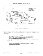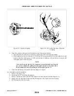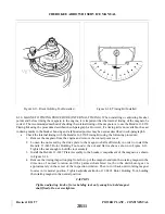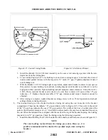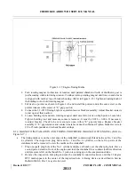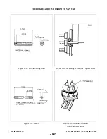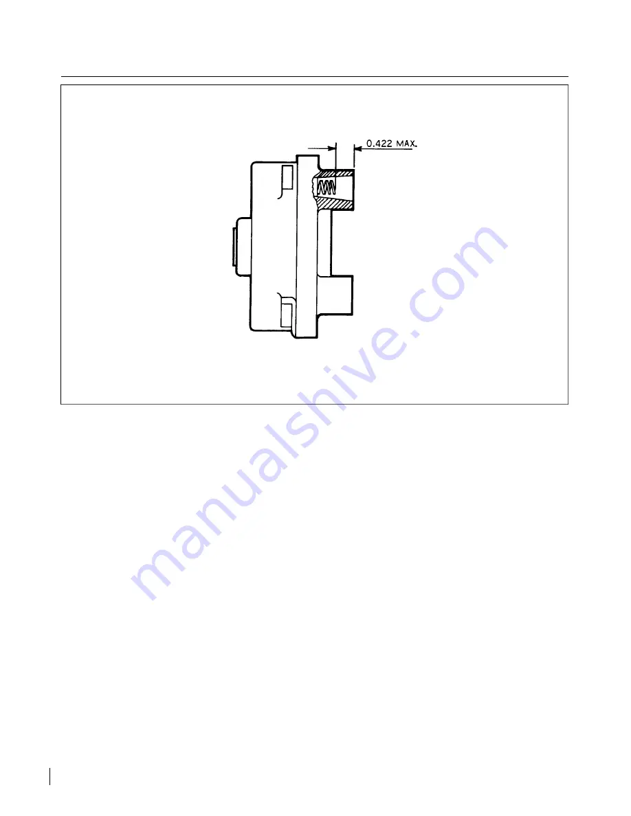
Figure 8-9. Contact Spring Inspection.
c.
Should the trouble appear definitely associated with the magneto, the most effective measure is to
install a replacement magneto which is known to be in satisfactory condition and send the suspected
unit to the overhaul shop for test and repair.
d. Should this not be possible, a visual inspection may disclose the source of trouble. Remove the harness
outlet plate from the magneto. Inspect for the presence of moisture and foreign matter on the rubber
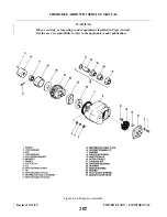
grommet and high tension outlet side of the distributor block. Check height of block contact springs.
The top of the spring must not be more than 0.422 of an inch below the top of the tower as shown in
Figure 8-9. If the springs are broken or corroded, replace them.
e.
Inspect the distributor block for cracks or burned areas. The wax coating on the block should not be
removed. Do not use solvents.
f.
Check for excess oil in the breaker compartment. If present, it may mean a bad oil seal or oil seal
bushing at the drive end. Check the magneto manufacturer’s overhaul procedure.
g. Remove the breaker cover and harness securing screws and nuts and separate cover from magneto
housing. Check contact assemblies to see that cam follower is securely riveted to its spring. Examine
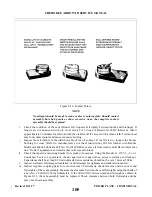
the contact points for excessive wear or burning. Figure 8-10 shows how the average contact point will
look when surfaces are separated for inspection. Desired contact surfaces have a dull gray, sandblasted
(almost rough) or frosted appearance over the area where electrical contact is made. This means that
points are worn in and mated to each other, thereby providing the best possible electrical contact and
highest efficiency of performance.
h. Minor irregularities or roughness of point surfaces are not harmful (refer to Figure 8-10, center),
neither are small pits or mounds, if not too pronounced. If there is a possibility of pit becoming deep
enough to penetrate pad, Figure 8-10, right, reject contact assembly.
Revised: 8/31/77
2B8
CHEROKEE ARROW III SERVICE MANUAL
POWER PLANT - CONTINENTAL
Summary of Contents for ARROW III
Page 4: ...THIS PAGE INTENTIONALLY LEFT BLANK 1A4...
Page 12: ...THIS PAGE INTENTIONALLY LEFT BLANK 1A12...
Page 94: ...Figure 4 2 Wing Installation Revised 2 13 89 1D22 CHEROKEE ARROW III SERVICE MANUAL STRUCTURES...
Page 171: ...lH3 INTENTIONALLY LEFT BLANK...
Page 172: ...lH4 INTENTIONALLY LEFT BLANK...
Page 286: ...THIS PAGE INTENTIONALLY LEFT BLANK Revised 2 13 89 2A8...
Page 528: ...INTENTIONALLY LEFT BLANK 2K10 THRU 2L24 2K10...

