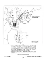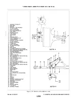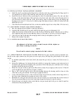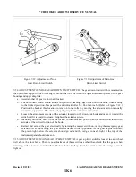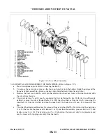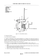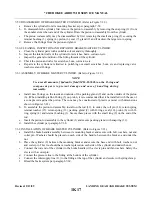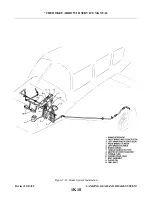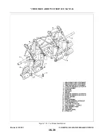
7-36. ADJUSTMENT OF MAIN GEAR DOWN LIMIT SWITCH. A gear down limit switch is mounted on a
bracket which is attached to the lower drag link of each main gear. The switch should be adjusted to allow it to
actuate thus turning on the green indicator light within the cockpit when the downlock hook has entered the
locked position and is within .025 to .035 of an inch of contacting the downlock pin. (Refer to Figure 7-13.)
Adjustment of the switch may be as follows:
a .
Ascertain that the main gear downlock is properly adjusted as described in Paragraph 7-26.
b .
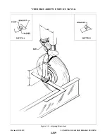
Raise the airplane on jacks. (Refer to Jacking, Section II.)
c .
Ascertain that the landing gear is down and pressure is relieved from the hydraulic system. To relieve
pressure, hold down the emergency extender lever.
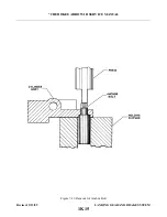
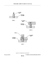
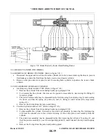
d . Raise the downlock hook assembly and place a .030 of an inch feeler gauge between the horizontal
surface of the hook that is next to the switch. (the surface that contacts the downlock pin) and the
rounded surface of the pin. Lower the hook and allow it to rest on the feeler gauge.
e .
Loosen the attaching screws of the switch and, while pushing up on the center of the link assembly, rotate
the switch toward the hook until it is head to actuate. Retighten the attaching screws of the switch.
f .
Manually move the hook assembly up from the pin until the hook nearly disengages from the pin. Then,
with pressure against the bottom of the link assembly, move back to ascertain that the switch actuates
within .025 to .035 of an inch of full lock.
g . Retract and extend the gear by turning the master switch on, raising the emergency gear extension lever
and moving the gear selector handle to the up position. As the gear begins to retract, the green light
below the selector should go out and the red gear unsafe light at the top of the instrument panel should
come on.
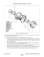
7-37. ADJUSTMENT OF LANDING GEAR SAFETY SWITCH (SQUAT SWITCH). The landing gear safety
switch, located on the left main gear housing is adjusted so that the switch is actuated within the last quarter of an
inch of gear extension.
a .
Compress the strut until 7.875 inches is obtained between the top of the gear fork and the bottom of the
gear housing. Hold the gear at this measurement.
b . Adjust the switch down until it actuates at this point. Secure the switch.
c .
Extend and then compress the strut to ascertain that the switch will actuate within the last quarter of an
inch of oleo extension.
WA R N I N G
Applicable to airplanes that are in compliance with Piper Service Bulletin
886A, Part II.
7-38. ADJUSTMENT OF GEAR BACK-UP EXTENDER ACTUATOR SWITCH. The back-up gear extender
actuator switch is mounted on the extender unit located under the bottom section of the rear seat. Inasmuch as the
switch is a component of the back-up extender, instructions for the adjustment of the switch will be found with
the adjustment instructions for the extender as found in Section VI.
7-39. LANDING GEAR WARNING SWITCHES (THROTTLE SWITCHES).
7-40. LANDING GEAR UP/POWER REDUCED WARNING SWITCH. The gear up/power reduced warning
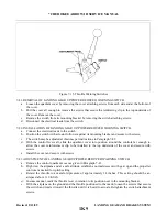
switch is within the control quadrant below the throttle control lever. (Refer to Figure 7-15.) This switch will
actuate the warning horn and red light simultaneously when the landing gear is not down and locked and the
throttle is reduced to the below 14 inches of manifold pressure.
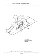
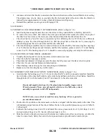
7-40a. LANDING GEAR UP/FLAP TORQUE TUBE CAM WARNING SWITCH. (All aircraft with back-up
gear extender disabled, or PA - 2 8 R - 2 0 1 / 2 0 l T, S/N’s 2837001 & 2803001 and up.) Any flap selection in excess of
10 degrees, or beyond the first notch, will activate the warning horn and red light simultaneously. Adjust the
switch assembly so the roller remains within the cam slot and the switch remains open and when in excess of 10
degrees, the roller exits the slow and allows the switch to close giving the landing gear up warning indication
(Refer to Figure 7- 14.)
Revised: 2/13/89
1K7
* CHEROKEE ARROW III SERVICE MANUAL
LANDING GEAR AND BRAKE SYSTEM
Summary of Contents for ARROW III
Page 4: ...THIS PAGE INTENTIONALLY LEFT BLANK 1A4...
Page 12: ...THIS PAGE INTENTIONALLY LEFT BLANK 1A12...
Page 94: ...Figure 4 2 Wing Installation Revised 2 13 89 1D22 CHEROKEE ARROW III SERVICE MANUAL STRUCTURES...
Page 171: ...lH3 INTENTIONALLY LEFT BLANK...
Page 172: ...lH4 INTENTIONALLY LEFT BLANK...
Page 286: ...THIS PAGE INTENTIONALLY LEFT BLANK Revised 2 13 89 2A8...
Page 528: ...INTENTIONALLY LEFT BLANK 2K10 THRU 2L24 2K10...

