SECTION VIIIA
POWER PLANT
LYCOMING
(PA-28R-201)
WARNING
When servicing or inspecting vendor equipment installed in Piper Aircraft,
it is the user’s responsibility to refer to the applicable vendor publication.
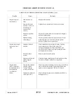
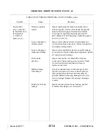
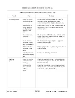
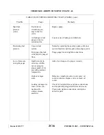
8A-1. INTRODUCTION. This section covers the power plant used in PA-28R-201 airplanes and is comprised
of instructions for the removal, minor repair, service and installation of the propeller, propeller governor,
engine, induction system, fuel injector, fuel air bleed nozzle, ignition system and lubrication system.
For further instructions on major repairs, consult the appropriate publication of the engine or component
manufacturer.
8A-1a. STANDARD PRACTICES-ENGINE. The following suggestions should be applied wherever they are
needed when working on the power plant.
The following suggestions should be applied wherever they are needed when working on the power plant.
a.
To ensure proper reinstallation and/or assembly, tag and mark all parts, clips, and brackets as to their
location prior to their removal and/or disassembly.
b. During removal of various tubes or engine parts, inspect them for indications of scoring, burning or
other undesirable conditions. To facilitate reinstallation, observe the location of each part during
removal. Tag any unserviceable part and/or units for investigation and possible repair.
c.
Extreme care must be taken to prevent foreign matter from entering the engine, such as lockwire,
washers, nuts, dirt, dust, etc. This precaution applies whenever work is done on the engine, either on or
off the aircraft. Suitable protective caps, plugs, and covers must be used to protect all openings as they
are exposed.
NOTE
Dust caps used to protect open lines must always be installed OVER the
tube ends and NOT IN the tube ends. Flow through the lines may be
blocked off if lines are inadvertently installed with dust caps in the tube
ends.
d. Should any items be dropped into the engine, the assembly process must stop and the item removed,
even though this may require considerable time and labor. Ensure that all parts are thoroughly clean
before assembling.
e.
Never reuse any lockwire, lockwashers, tablocks, tabwashers or cotter pins. All lockwire and cotter
pins must fit snugly in holes drilled in studs and bolts for locking purposes. Cotter pins should be
installed so the head fits into the castellation of the nut, and unless otherwise specified, bend one end
of the pin back over the stud or bolt and the other end down flat against the nut. Use only corrosion
resistant steel lockwire and/or cotter pins. Bushing plugs shall be lockwired to the assembly base or
case. Do not lockwire the plug to the bushing.
f.
All gaskets, packings and rubber parts must be replaced with the new items of the same type at
reassembly. Ensure the new nonmetallic parts being installed show no sign of having deteriorated in
storage.
g. When installing engine parts which require the use of a hammer to facilitate assembly or installation,
use only a plastic or rawhide hammer.
Revised: 2/13/89
2C19
POWER PLANT - LYCOMING
Summary of Contents for ARROW III
Page 4: ...THIS PAGE INTENTIONALLY LEFT BLANK 1A4...
Page 12: ...THIS PAGE INTENTIONALLY LEFT BLANK 1A12...
Page 94: ...Figure 4 2 Wing Installation Revised 2 13 89 1D22 CHEROKEE ARROW III SERVICE MANUAL STRUCTURES...
Page 171: ...lH3 INTENTIONALLY LEFT BLANK...
Page 172: ...lH4 INTENTIONALLY LEFT BLANK...
Page 286: ...THIS PAGE INTENTIONALLY LEFT BLANK Revised 2 13 89 2A8...
Page 528: ...INTENTIONALLY LEFT BLANK 2K10 THRU 2L24 2K10...

