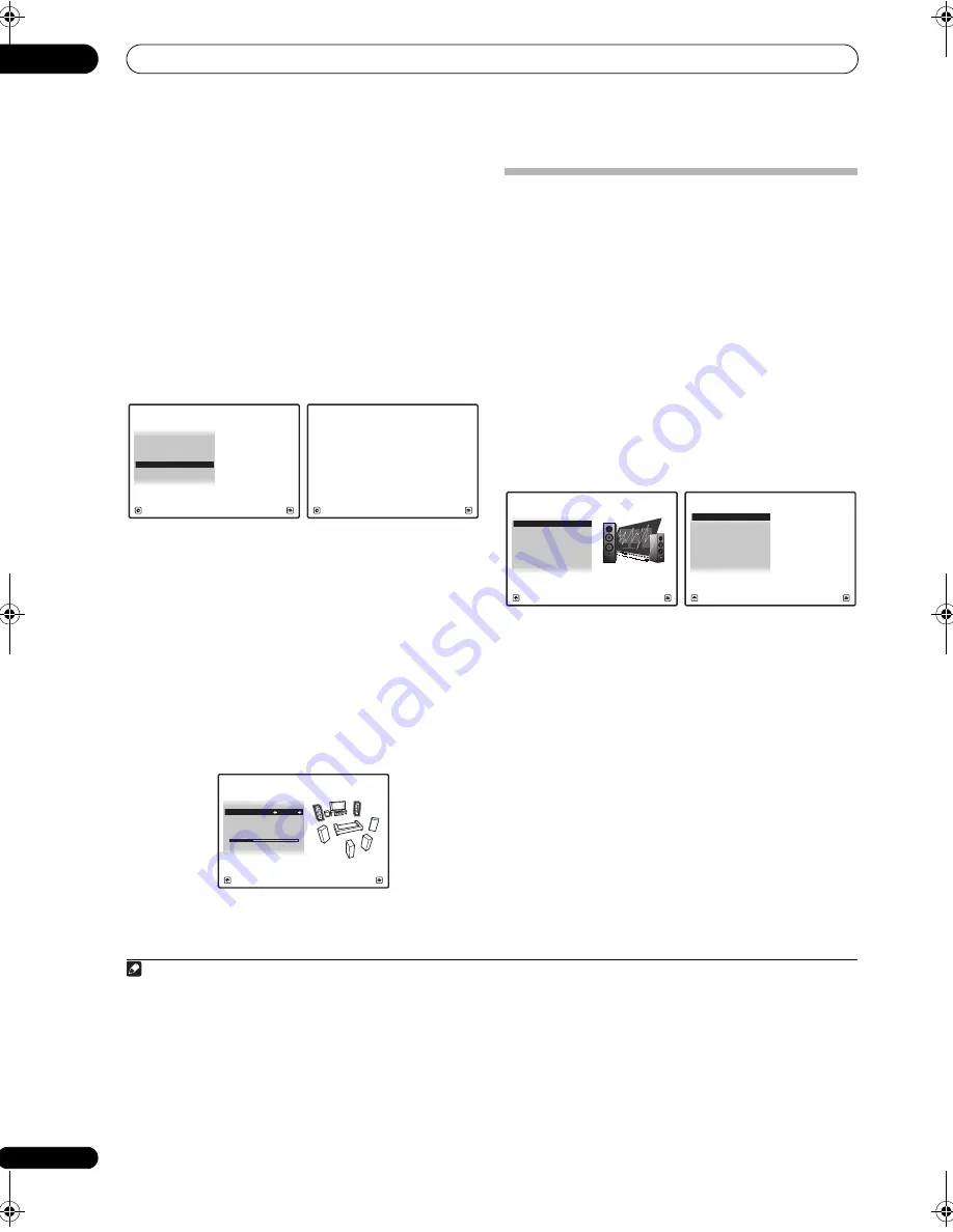
The Advanced MCACC menu
11
118
en
numerical value of the distance, actually move the
physical positions of the speakers to fine-adjust (the
subwoofer cannot be adjusted). The input from the
microphone is indicated on the screen. Fine-adjust the
positions of the speakers so that the gauge reading is
maximum. The detailed distance adjustments that were
previously performed by skilled installers by ear can
easily be performed watching the gauge on the monitor.
Place the microphone in the same position as when the
microphone was connected and the Full Auto MCACC
operation was performed.
1
Select ‘Precision Distance’ from the Manual
MCACC setup menu.
2
Fine-adjust the positions of the speakers in
sequence, starting from the front right channel.
1
Test pulses are output from the speaker for the selected
channel and from one other speaker. Move the position
of the selected speaker
1
/
2
inch towards or away from the
microphone. Watch the screen when doing so, and fine-
adjust the positions of the speakers so that the gauge
reading is maximum. Also, the channel serving as the
standard differs according to the channel being
adjusted. Do not move the speaker serving as the
standard channel.
The maximum gauge reading is 10.0. (If the reading stays
under 10.0, adjust the speaker for the maximum value.)
3
When you’re finished, press RETURN.
You will return to the Manual MCACC setup menu.
Checking MCACC Data
At the procedure of
Automatically setting up for surround
sound (Auto MCACC & Full Band Phase Control)
on
page 46, the procedure of
Automatic MCACC (Expert)
on
page 110 or after fine-adjusting at
Manual MCACC setup
on page 112, you can check your calibrated settings
using the GUI screen or, if a computer is connected, on
the computer’s screen.
1
Set the remote control to the receiver operation
mode, then press HOME MENU.
A Graphical User Interface (GUI) screen appears on your
TV. Use
///
and
ENTER
to navigate through the
screens and select menu items. Press
RETURN
to
confirm and exit the current menu.
2
Select ‘MCACC Data Check’ from the HOME
MENU.
3
Select the setting you want to check.
•
Speaker Setting
– Used to check the settings of the
speaker systems. See
Speaker Setting
below for more
on this.
•
Channel Level
– Used to check the output level of the
different speakers. See
Channel Level
below for more
on this.
•
Speaker Distance
– Used to check the distance to
the different speakers. See
Speaker Distance
below
for more on this.
•
Standing Wave
– Used to check the standing wave
control filter settings. See
Standing Wave
on page 119
for more on this.
•
Acoustic Cal EQ
– Used to check the calibration
values of the listening environment’s frequency
response. See
Acoustic Cal EQ
on page 120 for more
on this.
Note
1 • If the microphone is placed in a different position from when the Auto MCACC procedure was performed, it may not be possible to adjust properly. In
this case, we recommend performing the procedure at
Fine Speaker Distance
on page 114 in the Auto MCACC custom measurements, then performing the
adjustment described here without moving the microphone.
• The adjustment here is for adjusting for an error of 1/2 inch or less (not adjustable with the Auto MCACC Setup). 0.0 may be displayed after distance
correction with the Auto MCACC Setup, but even in this case this adjustment allows you to optimize the correction. Note that if the Auto MCACC Setup is
performed after completing the fine-adjustment here, the correction precision will drop to about 1/2 inch.
• Like with the Auto MCACC Setup, perform this adjustment in as quiet an environment as possible. 0.0 will be displayed if abrupt noise is input during the
adjustment.
• The distance for all the channels can only be made uniform even if the
R
(front right) channel is adjusted in the proper order.
• Be very careful not to tip the speakers over when moving them.
• The result of the adjustment performed here can be checked by listening to the test pulses output at the
Precision Distance (SC-27 only)
on page 117 (the
test pulses will be more centrally positioned between the speakers than before the adjustment was performed). Be careful not to change the distance values
at this time.
1. Fine Channel Level
2. Fine SP Distance
3. Standing Wave
1c.Manual MCACC
4. EQ Adjust
5. EQ Professional
A/V RECEIVER
Exit
Return
6. Precision Distance
CAUTION
Loud test tones will be output.
Please wait...**
1c6.Precision Distance
A/V RECEIVER
Exit
Cancel
A/V RECEIVER
Exit
Finish
Reference Ch :
L
1c6.Precision Distance
Adjust Ch
:
R
2.0
1. Advanced MCACC
2. MCACC Data Check
3. Data Management
4. System Setup
Exit
Return
HOME MENU
A/V RECEIVER
a. Speaker Setting
b. Channel Level
c. Speaker Distance
2.MCACC Data Check
d. Standing Wave
e. Acoustic Cal EQ
f. Group Delay
g. Output PC
A/V RECEIVER
Exit
Return
SC-27_25.book Page 118 Monday, April 6, 2009 7:15 PM


