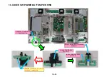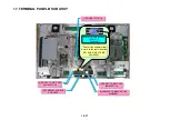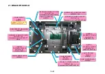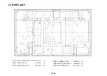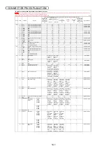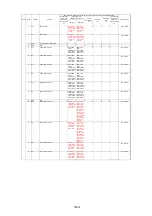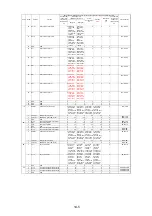
AU
PV
TM
FAFB
PM
PN
PW
SW
RS
PW
PM
PN
PA
PV
PA
AU
AC
TR
TS
TS
PH
PD
LD
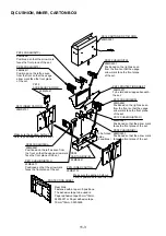
Pass the LD from the bottom.
RS
FC
PH
PD
SW
AU
Pass AU,AD PM PN and PV.
(AU is made into the top.)
x4, Pass TS.
x2, Pass AU and PA.
Excessive AU line length is adjusted.
x2, Pass AU.
TR
TM
Pass
2 turns
of GND.
Pass
2 turns
of AU.
Pass
2 turns
of PA.
Pass
2 turns
of TR.
Pass PD and PH.
Pass
2 turns
of TM.
Pass
2 turns
of TS.
Pass the AD and fasten it with
the attached harness band.
(Label side) AD
Pass the PW beneath the RS.
Fasten both AU and TM with the
lead clampers.
Reduce the distance toward the ferrite core.
Excessive AC line length is adjusted.
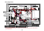
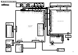
Wiring Diagram (Set)
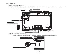
CCD board of PX-61XM3A/PX-61XR3A : Try to push the bush rivet and the connector, and confirm that there
is no floating of parts.
x2, Pass TR and TS.
Pass TR,TS and FC.
Pass TR and FC.
Pass TR,FB and FC.
Pass TM and TR.
Pass PH.
Pass TR,FB and FC.
Pass PH and PD.
Pass PD.
x2, Pass PD.
Pass TM,FB and FC.
Pass TM,FB and FC.
Pass TM,FA FB and FC.
Pass FA and FB.
Pass PV,PM PN and PA.
Pass GND and AC.
Pass GND and AC.
Pass AC.
Pass PV.
Pass
3 turns
of GND.
Pass PW.
Pass RS.
Pass SW.
Pass RS.
Pass PW.
Pass AU and PA.
Pass AD.
Pass RS and SW.
Pass SW.
Pass LD.
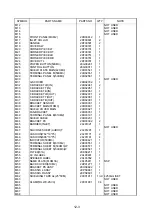
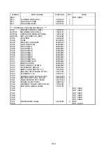
PARTS NAME (PARTS NO.)
Q'TY
FERRITE CORE
ESD-R-19 (6S170007)
1
CLAMP
UAMS-05-2 (29C01751)
7
LCT-1S (29C00551)
1
RBWS-5N (29C01741)
2
SFT-72SNB-026K (6S170003)
3
ZCAT2032-930 (6S170005)
10
FERRITE CORE
PARTS NAME (PARTS NO.) Q'TY
FERRITE CORE
CLAMP
CLAMP
EDGING SADDLE EDS-1208U (29C00461)
1
CLAMP
RLWC-2SV0 (29C01901)
34
LEAD CLAMP
D8.3 (24C00101)
1
CLAMP
RFCC-625 (29C01721)
1
PARTS NAME (PARTS NO.) Q'TY
Pass PN and PM.
Pass PV,PM and PN.
10-26
Summary of Contents for Elite PureVision PRO 1410HD
Page 5: ...2 3 ...
Page 6: ...2 4 ...
Page 8: ...SPECIFICATIONS PDP 614MX 3 1 ...
Page 9: ... PRO 1410HD 3 2 ...
Page 10: ...TABLE OF SIGNAL SUPPORTED PDP 614MX 4 1 ...
Page 11: ...4 2 ...
Page 12: ...4 3 PRO 1410HD ...
Page 13: ...4 4 ...
Page 14: ...PANEL FACILITIES 5 1 PDP 614MX ...
Page 15: ...5 2 ...
Page 16: ...5 3 PRO 1410HD ...
Page 17: ...5 4 ...
Page 32: ...7 11 ...
Page 44: ...All white signal All white signal 8 12 ...
Page 50: ... Fig 1 CCD PWB Pattern Diagram A B D E 3 3V 6V C 8 18 ...
Page 51: ...8 19 Check point MAIN PWB ...
Page 52: ...8 20 232C PWB ...
Page 53: ...8 21 CLT PWB ...
Page 54: ...8 22 PWR PWB ...
Page 55: ...8 23 LED PWB ...
Page 56: ...8 24 SENB PWB ...
Page 57: ...8 25 SENC PWB ...
Page 58: ...8 26 SEND PWB ...
Page 59: ...AUDIO PWB 8 27 ...
Page 60: ...8 28 CCD PWB PX A only ...

