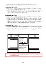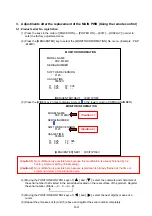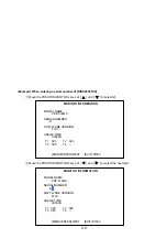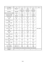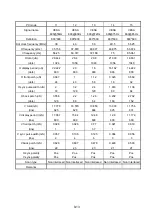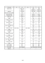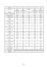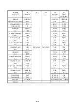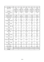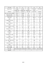
Repeat the procedures of and above, and enter all inputs of [
DISS00001XX
] from the left side.
(7) Following the above, setting must be carried out without fail according to “3-2. Factory shipment
setting (Initial setting)”
3-2.Factory shipment setting (Initial setting)
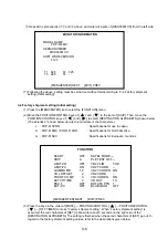
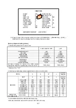
(1) Press the [MENU/ENTER] ke to select the [FUNCTION] menu.
(2) Move the POSITION/CONTROL keys of [ ] and [ ] to the item of [SHIP]. Then, move the
POSITION/CONTROL keys of [ ] and [ ] to select [DESTINATION ALPHABETS] shown below.
(The asterisks * shown below denote the numerals or the characters.)
J : P
DP-615PRO
: Specifications for use in Japan
A : P
DP-614MX / PRO-1410HD
: Specifications for North America
G : P
DP-615EX
: Specifications for European countries
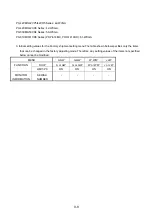
(3) Press the keys in the order of [MUTE]
→
POSITION/CONTROL [ ]
→
POSITION/CONTROL
[ ]
→
[OFF TIMER] to make “Factory shipment setting”. When “Factory shipment setting” is
executed, the red characters of [SET] is shown for about 5 seconds on the right side of the
[DESTINATION ALPHABETS]. The setting is finished when these red characters of [SET] go out. In
regard to the factory shipment setting values, refer to the descriptions given below.
FUNCTION
SCART
OFF
SAFEL MODE ---
SHIP
A
PLE TEST OFF --
LIMIT-VD OFF
VD2
VLIM
5HZ
LIMIT-PC ON
VD2
YCORB
--
GAMMA MD
12
VD2 YCOREN ON
VOL OFFSET
2
VD2 CORB
--
FHCRT COMP
3
VD2 COREN
ON
ACTVH TIME
2
VD OUT
10
PSC-T OFF
ROTATE
PTN
1
EXT-PC OFF
BLUE
GAIN
OFF
[MENU/ENTER] NEXT [EXIT] PREV
MONITOR INFORMATION
MODEL
NAME
:
P
DP
-61
4MX
SERIAL/NUMBER
:
00001XX
DISS
SOFT WARE VERSION
:
F123
USAGE
TIME
:
00000H
T1 025 T2 025
T3 025 T4 - -
[MENU/ENTER] NEXT [EXIT] PREV
9-6
Summary of Contents for Elite PureVision PRO 1410HD
Page 5: ...2 3 ...
Page 6: ...2 4 ...
Page 8: ...SPECIFICATIONS PDP 614MX 3 1 ...
Page 9: ... PRO 1410HD 3 2 ...
Page 10: ...TABLE OF SIGNAL SUPPORTED PDP 614MX 4 1 ...
Page 11: ...4 2 ...
Page 12: ...4 3 PRO 1410HD ...
Page 13: ...4 4 ...
Page 14: ...PANEL FACILITIES 5 1 PDP 614MX ...
Page 15: ...5 2 ...
Page 16: ...5 3 PRO 1410HD ...
Page 17: ...5 4 ...
Page 32: ...7 11 ...
Page 44: ...All white signal All white signal 8 12 ...
Page 50: ... Fig 1 CCD PWB Pattern Diagram A B D E 3 3V 6V C 8 18 ...
Page 51: ...8 19 Check point MAIN PWB ...
Page 52: ...8 20 232C PWB ...
Page 53: ...8 21 CLT PWB ...
Page 54: ...8 22 PWR PWB ...
Page 55: ...8 23 LED PWB ...
Page 56: ...8 24 SENB PWB ...
Page 57: ...8 25 SENC PWB ...
Page 58: ...8 26 SEND PWB ...
Page 59: ...AUDIO PWB 8 27 ...
Page 60: ...8 28 CCD PWB PX A only ...

