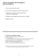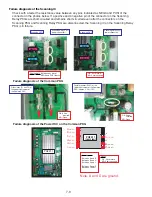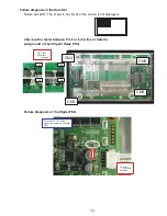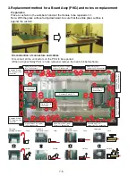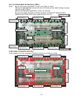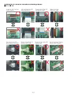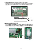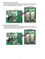
HOW TO DIAGNOSE THE PDP MODULE
(PDP-NP61C2MF01)
1. List of tools required for repair
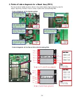
2. Points of failure diagnosis for a Board Assy (PKG)
3. Replacement method of a Board Assy (PKG)
and notes on replacement
4. Adjustments after replacement of parts in the module
5. Operation check
1. List of tools required for repair
a) Phillips screwdriver : For detaching/reattaching PKGs
b) Antistatic wrist strap :
To be used when electronic components, such as PKGs, are to be handled
c) Signal generator (PC, etc.) : For voltage adjustment and display check
d) Powe : For voltage adjustment and display check
f ) Tester : For cable check, voltage adjustment, etc.
g) Cushion : To be used when the PKGs are to be replaced
Note: Be sure to wear a wrist strap when you detach/reattach PKGs (Board Assy) to protect
electronic components from being damaged by electrostatic charges.
7-1
Summary of Contents for Elite PureVision PRO 1410HD
Page 5: ...2 3 ...
Page 6: ...2 4 ...
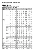
Page 8: ...SPECIFICATIONS PDP 614MX 3 1 ...
Page 9: ... PRO 1410HD 3 2 ...
Page 10: ...TABLE OF SIGNAL SUPPORTED PDP 614MX 4 1 ...
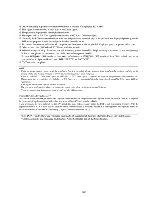
Page 11: ...4 2 ...
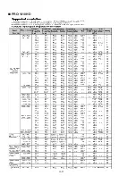
Page 12: ...4 3 PRO 1410HD ...
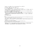
Page 13: ...4 4 ...
Page 14: ...PANEL FACILITIES 5 1 PDP 614MX ...
Page 15: ...5 2 ...
Page 16: ...5 3 PRO 1410HD ...
Page 17: ...5 4 ...
Page 32: ...7 11 ...
Page 44: ...All white signal All white signal 8 12 ...
Page 50: ... Fig 1 CCD PWB Pattern Diagram A B D E 3 3V 6V C 8 18 ...
Page 51: ...8 19 Check point MAIN PWB ...
Page 52: ...8 20 232C PWB ...
Page 53: ...8 21 CLT PWB ...
Page 54: ...8 22 PWR PWB ...
Page 55: ...8 23 LED PWB ...
Page 56: ...8 24 SENB PWB ...
Page 57: ...8 25 SENC PWB ...
Page 58: ...8 26 SEND PWB ...
Page 59: ...AUDIO PWB 8 27 ...
Page 60: ...8 28 CCD PWB PX A only ...


