No signal
With signal
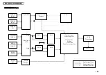
Signal direction
Main power ON
(POWER button ON)
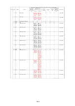
★
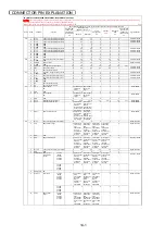
Pin No.
Pin name
Function
Standby
★★★
Power
management
★★
Main power
OFF
★★
AC power OFF
(Power cord
pulled out of
the wall outlet)
★★
AC power ON
(Power cord
connected to
the wall outlet)
★★
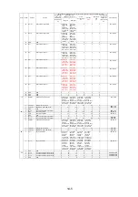
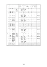
Basic operation (Numerical unit: Vdc; except for the case when units are individually indicated)
Name
5
PS+
PSS input PS+
0
PSS LVDS
serial differen
tial PS+ input
0Vac; Bias
1.1Vdc
PSS LVDS
serial differen
tial PS+ input
0.3Vac; Bias
1.25Vdc
0
0
0
-
PDP
→
MAIN
6
PS-
PSS input PS-
0
PSS LVDS
serial differen
tial PS+ input
0Vac; Bias
1.4Vdc
PSS LVDS
serial differen
tial PS+ input
0.3Vac; Bias
1.25Vdc
0
0
0
-
PDP
→
MAIN
7
MSEL
42V5 compatible interface OFF
0
0
0
0
0
0
-
-
8
GND
GND
0
0
0
0
0
0
-
-
9
RH+
OSD system output H+
0 OSD LVDS
serial
differential H+
output 0Vac;
Bias 1.1Vdc
OSD LVDS
serial
differential H+
output 0Vac;
Bias 1.1Vdc
0
0
0
-
MAIN
→
PDP
10
RH-
OSD system output H–
0 OSD LVDS
serial
differential H-
output 0Vac;
Bias 1.4Vdc
OSD LVDS
serial
differential H-
output 0Vac;
Bias 1.4Vdc
0
0
0
-
MAIN
→
PDP
11
RG+
OSD system output G+
0 OSD LVDS
serial
differential G+
output 0.3Vac;
Bias 1.25Vdc
OSD LVDS
serial
differential G+
output 0.3Vac;
Bias 1.25Vdc
0
0
0
-
MAIN
→
PDP
12
RG-
OSD system output G-
0 OSD LVDS
serial
differential G-
output 0.3Vac;
Bias 1.25Vdc
OSD LVDS
serial
differential G-
output 0.3Vac;
Bias 1.25Vdc
0
0
0
-
MAIN
→
PDP
13
RF+
Mode system output F+
0 Video mode
LVDS serial
differential F+
output 0.3Vac;
Bias 1.25Vdc
Video mode
LVDS serial
differential F+
output 0.3Vac;
Bias 1.25Vdc
0
0
0
-
MAIN
→
PDP
14
RF-
Mode system output F-
0 Video mode
LVDS serial
differential F-
output 0.3Vac;
Bias 1.25Vdc
Video mode
LVDS serial
differential F-
output 0.3Vac;
Bias 1.25Vdc
0
0
0
-
MAIN
→
PDP
15
GND
GND
0
0
0
0
0
0
-
-
16
RE+
Video system output E+
0
Video mode
LVDS serial
differential E+
output 0Vac;
Bias 1.1Vdc
Video mode
LVDS serial
differential E+
output 0Vac;
Bias 1.1Vdc
* Only for the
PX-42VP4
Series, 0.3Vac
and bias 1.25
Vdc in theater
mode when
60Hz motion
pictures are
displayed.
0
0
0
-
MAIN
→
PDP
17
RE-
Video system output E-
0
Video mode
LVDS serial
differential E-
output 0Vac;
Bias 1.4Vdc
Video mode
LVDS serial
differential E-
output 0.3Vac;
Bias 1.25Vdc
* Only for the
PX-42VP4
Series, 0.3Vac
and bias 1.25
Vdc in theater
mode when
60Hz motion
pictures are
displayed.
0
0
0
-
MAIN
→
PDP
18
RD+
Video system output D+
0
Video mode
LVDS serial
differential D+
output 0Vac;
Bias 1.1Vdc
Video mode
LVDS serial
differential D+
output 0.3Vac;
Bias 1.25Vdc
0
0
0
-
MAIN
→
PDP
19
RD-
Video system output D–
0
Video mode
LVDS serial
differential D-
output 0Vac;
Bias 1.4Vdc
Video mode
LVDS serial
differential D-
output 0.3Vac;
Bias 1.25Vdc
0
0
0
-
MAIN
→
PDP
14-4
Summary of Contents for Elite PureVision PRO 1410HD
Page 5: ...2 3 ...
Page 6: ...2 4 ...
Page 8: ...SPECIFICATIONS PDP 614MX 3 1 ...
Page 9: ... PRO 1410HD 3 2 ...
Page 10: ...TABLE OF SIGNAL SUPPORTED PDP 614MX 4 1 ...
Page 11: ...4 2 ...
Page 12: ...4 3 PRO 1410HD ...
Page 13: ...4 4 ...
Page 14: ...PANEL FACILITIES 5 1 PDP 614MX ...
Page 15: ...5 2 ...
Page 16: ...5 3 PRO 1410HD ...
Page 17: ...5 4 ...
Page 32: ...7 11 ...
Page 44: ...All white signal All white signal 8 12 ...
Page 50: ... Fig 1 CCD PWB Pattern Diagram A B D E 3 3V 6V C 8 18 ...
Page 51: ...8 19 Check point MAIN PWB ...
Page 52: ...8 20 232C PWB ...
Page 53: ...8 21 CLT PWB ...
Page 54: ...8 22 PWR PWB ...
Page 55: ...8 23 LED PWB ...
Page 56: ...8 24 SENB PWB ...
Page 57: ...8 25 SENC PWB ...
Page 58: ...8 26 SEND PWB ...
Page 59: ...AUDIO PWB 8 27 ...
Page 60: ...8 28 CCD PWB PX A only ...

