


Commissioning
Operating Manual PSEN op2B/1 Series
1003357-EN-02
46
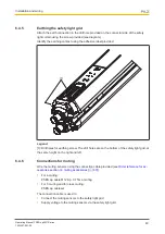
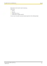
7.2.3
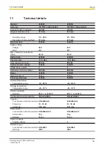
Muting sensor alignment
The following steps are only necessary if you are connecting muting sensors to the safety
light grid.
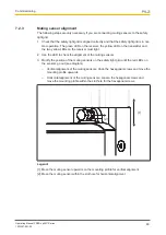
1. Check that the safety light grid is aligned correctly and that the safety light grid is in nor-
mal operation. The green LED on the receiver, the yellow LED on the transmitter and
the two yellow LEDs on the receiver must light.
2. Use the LED to check the alignment of the muting sensors.
3. Modify the position of the muting sensors on the safety light grid until the red LEDs on
the sensors go out (see diagram).
– Vertical alignment of the muting sensors: Undo the hexagonal screws and move the
mounting profile upwards.
– Horizontal alignment of the muting sensors: Loosen the hexagonal screws and
move the mounting profile within the slot hole for the hexagonal screws.
[1]
[2]
Legend:
[1]: Move the muting sensor upwards on the mounting profile for vertical alignment
[2]: Move the muting sensor within the slot hole for horizontal alignment


