


Installation and wiring
Operating Manual PSEN op2B/1 Series
1003357-EN-02
41
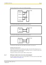
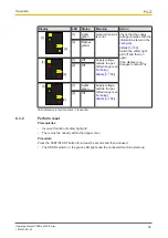
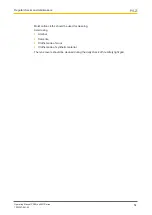
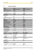
Wire the muting sensors as shown in the following diagrams.
2
4
Muting A1
Muting A2
Muting B1
Muting B2
Muting sensor
Safety light grid
Fig.: Wiring of 4 muting sensors on the receiver's 5-pin connector
Muting sensor
Safety light grid
2
4
Muting A1
Muting B1
Fig.: Wiring of 2 muting sensors on the receiver's 5-pin connector
Muting sensor
Safety light grid
2
4
Muting A1
Muting B2
Fig.: Wiring of 2 muting sensors for cross muting on the receiver's 5-pin connector
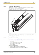
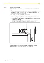
Earthing of muting sensors
Attach the earth connection in the drill hole provided on the side of the muting sensors, us-
ing the screw provided. The drill holes for the earthing screw are on the right and left side of
the muting sensors, at the same height.
Identify the earthing contact using the adhesive label provided.
6.4.7
Wiring of external sensors on the safety light grid
Wire the external muting sensors in the control cabinet in accordance with the details stated
under
Connections for muting [
40]
.


