


Installation and wiring
Operating Manual PSEN op2B/1 Series
1003357-EN-02
35
6
Installation and wiring
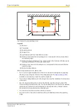
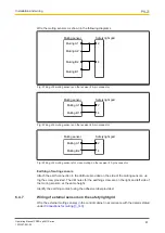
Please note the following when affixing the transmitter and receiver:
}
The units' optical surfaces must be arranged so that they are facing each other.
}
The connector sides of both units must be positioned on the same side and at the same
height.
}
The distance between the units must be within the operating range of the relevant unit
(see
Technical details [
56]
).
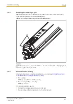
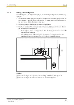
6.1
Attach safety light grid without muting sensors to mounting
surface
Procedure
Attach the safety light grid
to the mounting surface. Use the
two threaded pins supplied to attach the units.
1. Insert the threaded pins into the grooves on both units.
2. Place a mounting bracket on the pins and secure the
bracket with the pins.
3. Use screws to provisionally fix the mounting bracket to
the mounting surface.
4. Align the safety light grid
approximately and then
tighten up the screws on the mounting bracket.
Where vibration is particularly strong
}
threaded pins and
}
mounting bracket
should be used with vibration dampers.
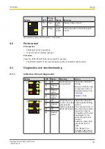
6.2
Conversion of safety light grids without muting sensors
}
Allocation of muting sensors to transmitter and receiver:
– The passive muting sensor PSEN op Reflector must be installed on the transmitter.
– The active muting sensor PSEN op Reflex must be installed on the receiver.
Requirement for installing the muting sensors on the safety light grid:
}
The PSEN op muting bracket kit must be attached to both units of the safety light grid.
}
The safety light grid
must already be attached to the mounting surface.


