


Installation and wiring
Operating Manual PSEN op2B/1 Series
1003357-EN-02
37
6.4
Wiring
6.4.1
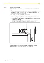
General guidelines
}
Never place connection cables close to or in contact with cables with the following char-
acteristics (motor supply, inverter or similar).
– High current ratings,
– Strong current fluctuations.
}
Use separate cables to connect the wires to the OSSDs on different safety light grids.
}
Do not connect contacts OSSD1 and OSSD2 in series or in parallel.
}
Connect the N/C contact on the TEST/START button to the supply voltage on the
safety light grid.
}
Connect the N/C contact on the EDM to the supply voltage on the safety light grid.
}
The safety light grid
is already equipped with internal filter capacitors. We would advise
against using additional external components.
Use the connection cable available as an accessory to wire the safety light grid (see
Order
reference for accessories [
59]
).
6.4.2
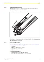
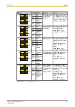
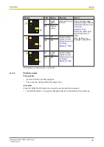
Connector pin assignment
Electrical connections to the transmitter and receiver are made via M12 connectors on both
units. These connectors are located on the bottom of the units.
1
2
3
4
5
Fig.: 5-pin connector on the receiver to connect muting sensors to the receiver on the safety light grid
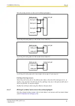
PIN Designation
Description
Cable colour
1 +24 VDC
Supply voltage for external muting sensor
Brown
2 Muting 2
Input signal for second muting sensor
White
3 0 VDC
Supply voltage for external muting sensor
Blue
4 Muting 1
Input signal for first muting sensor
Black
5 n.c.
-
Grey
}
n.c. = not connected


