


Installation and wiring
Operating Manual PSEN op2B/1 Series
1003357-EN-02
39
}
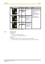
n.c. = not connected
1
2
3
4
5
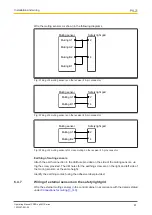
Fig.: 5-pin connector on the transmitter to connect the supply voltage for muting sensors to the trans-
mitter on the safety light grid
PIN Designation
Description
Cable colour
1
+24 VDC
Supply voltage for external muting sensor
Brown
2
n.c.
-
White
3
0 VDC
Supply voltage for external muting sensor
Blue
4
n.c.
-
Black
5
n.c.
-
Grey
}
n.c. = not connected
6.4.3
TEST/START button
Connect the N/C contact on the TEST/START button to the supply voltage on the safety
light grid.
6.4.4
EDM
Connect the N/C contact on the EDM to the supply voltage on the safety light grid.


