5.2.3.3
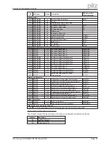
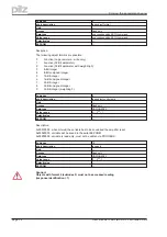
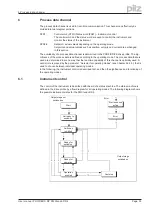
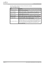
PNU 1002: manufacturer-specific status register
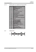
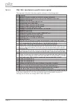
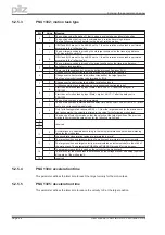
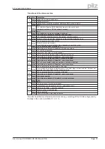
The assignment of the bits for the status register can be seen in the following table:
Bit
Description
0
Warning 1:
I²t threshold exceeded (set, as long as I
rms
is above the threshold)
1
Warning 2:
Ballast power exceeded (set, as long as the set ballast power is exceeded)
2
Warning 3:
Contouring error
3
Warning 4:
Threshold monitoring (field bus) active
4
Warning 5:
Mains supply phase missing
5
Warning 6:
Software limit-switch 1 has been activated
6
Warning 7:
Software limit-switch 2 has been activated
7
Warning 8:
Faulty motion task has been started
8
Warning 9:
No reference point was set at the start of the motion task
9
Warning 10:
PSTOP active
10
Warning 11:
NSTOP active
11
Warning 12:
Motor default values were loaded (HIPERFACE
®
only)
12
Warning 13:
Expansion card is not working properly
13
Warning 14:
SinCos commutation not carried out
14
Warning 15:
Speed - current table error INXMODE 35
15
Warning 16:
Reserve
16
Motion task active (is set as long as a position control task is active - motion task, jogging, homing).
17
Reference point set (is set after a homing run, or when an absolute position (multi-turn) encoder is used.
This is canceled when the amplifier is switched on, or when a homing run is started.
18
Actual position = home position (is set as long as the reference switch is activated).
19
InPosition (is set as long as the difference between the target position for a motion task and the actual
position is smaller than PEINPOS. The InPosition signal is suppressed if a following task is started at
the target position.
20
Position latch set (positive edge) – this is set if a rising edge is detected on the INPUT2 (IN2MODE=26)
that is configured as a latch. This is canceled if the latched position is read out (LATCH16/LATCH32)
21
—
22
Position 1 reached (is set if the configured condition for this signal (SWCNFG, SWE1, SWE1N) is met.
Depending on the configuration, this bit is set on exceeding SWE1, or going below SWE1, on reaching
the InPosition window SWE1...SWE1N or on leaving the InPosition window SWE1...SWE1N.
23
Position 2 reached (see above)
24
Position 3 reached (see above)
25
Position 4 reached (see above)
26
Initialization completed (is set if the internal initialization of the amplifier is completed).
27
—
28
Speed = 0 (is set as long as the motor speed is below the standstill threshold VEL0).
29
Safety relay has been triggered (is set as long as the safety relay is open – AS-Option)
30
Output stage enabled (is set when software and hardware enables are set).
31
Error present (is canceled when the amplifier is switched on, or if the function “Cancel error” is called.
In the process data, Bits 16 to 31 of the manufacturer-specific status register are given out.
Warnings 3 and 4 can be reset through Bit 13 in the control word.
Page 26
User manual PROFIBUS DP PMCtendo DD4
5 Using the parameter channel


