6.1.2
Status word (ZSW)
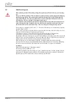
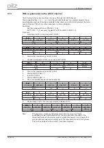
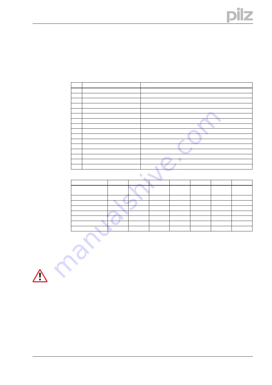
With the aid of the status word, the instrument state can be represented and the transmitted control
word can be verified. If an unexpected condition is reported, as the result of a transmitted control
word, then first of all the boundary conditions for the expected instrument state must be clarified
(e.g. enable of the output stage – ha software, application of the DC-link voltage).
The bits in the status word can be
mode-dependent
or
mode-independent.
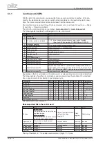
The following table describes the bit assignment in the status word.
Bit
Name
Commentary
0
Ready for switch-on
---
1
Switched on
---
2
Operation enabled
---
3
Error
see ASCII command ERRCODE
4
Voltage inhibited
---
5
Fast stop
---
6
Switch-on inhibit
---
7
Warning
see ASCII command STATCODE
8
Setpoint / actual value monitoring
only in position-control mode: contouring error indicator
9
Remote
not supported, fixed to 1
10
Setpoint reached
only in position mode: In Position
11
Limit active
not supported at present
12
Mode-dependent
used in ASCII-mode
13
Mode-dependent
used in ASCII-mode
14
Manufacturer-specific
used in ASCII-mode
15
Manufacturer-specific
reserved
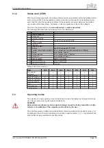
States of the status machine:
State
Bit 6
Bit 5
Bit 4
Bit 3
Bit 2
Bit 1
Bit 0
Not ready for
switch-on
0
X
X
0
0
0
0
Switch-on inhibit
1
X
X
0
0
0
0
Ready for switch-on
0
1
X
0
0
0
1
Ready for operation
0
1
X
0
0
1
1
Operation enabled
0
1
X
0
1
1
1
Error
0
X
X
1
X
X
X
Error response
0
X
X
1
0
0
0
Fast stop active
0
0
X
0
1
1
1
6.2
Operating modes
The selection of a new operating mode is described in detail in the chapter on the parameter chan-
nel. This procedure must be observed and adhered to.
WARNING
Appropriate precautionary measures against damage caused by faulty presentation of data
formats or normalization of the setpoints must be taken by the user.
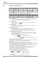
The possible operating modes are described below. Operating modes with a positive number (1,2)
are defined in the drive profile. Operating modes with a negative number (-1,-2...) are labeled in the
drive profile as being manufacturer-specific modes.
User manual PROFIBUS DP PMCtendo DD4
Page 39
6 Process data channel

