5.2.8.2
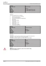
PNU 1458/1459: function of the digital outputs
These parameters can be used to configure the two digital outputs individually.
PWE
Function
PWE
Function
0
Off
14
PosREG.3
1
n_act<x
15
PosREG.4
2
n_act>x
16
Next-InPos
3
Mains-BTB
17
Error/Warn
4
Ballast
18
Error
5
Sw_end
19
DC_Link>x
6
Pos.>x
20
DC_Link<x
7
InPos
21
ENABLE
8
list<x
22
Zero-pulse
9
list>x
23
Reserve
10
S_fault
24
Ref_OK
11
I²t
28
PosREG. 0
12
PosREG.1
29
PosREG. 5
13
PosREG.2
5.2.9
Analog configuration
All settings for the analog inputs and outputs only become effective after being saved in the
EEPROM and then switching off and on again, or making a cold start of the PMCtendo DD4. The
significance of the functions can be seen in the user manual for the setup Software.
5.2.9.1
PNU 1500: configuration of the analog input functions
This parameter can be used to configure the two analog inputs together.
PWE
Function
0
Xsetp = SW1
1
N_setp = SW1, Isetp = SW2
2
unused
3
Xsetp = SW1, Ipeak = SW2
4
Xsetp = SW1 + SW2
5
Xsetp = SW1 * SW2
6
Electr. gearing
7
Icmd = SW1, nmax = SW2
8
Pcmd = SW1
9
Xcmd = SW1, Ferraris = SW2
5.2.9.2
PNU 1501/1506: configuration of the analog outputs
This parameter can be used to configure the two analog outputs individually.
PWE
Function
0
Off
1
n act
2
I act
3
n setp
4
I setp
5
S_fault
6
Slot
Page 32
User manual PROFIBUS DP PMCtendo DD4
5 Using the parameter channel

