EN 13
HTS5000W
Service Test Program
5.
5. Service Test Program
TEST
Activated with
ACTION
ROTARY
ENCODER TEST
Volume
Knob
Display shows value for 2 seconds.
Volume values increases or decreases in
steps of 1
until 0 (VOL MIN) or 40 (VOL MAX) is
reached.
LEAVE SERVICE
TEST PROGRAM
Disconnect
mains cord
To start service test program
open the tray with remote control
or front panel key, while plugging
in the mains cord press 2, 5, 8 on
remote control, the tray will close
by itself and the set will display
shown “S-Vxx-yy”
Display shows
“SERVICE”
followed by ROM version
“S-Vxx-yy”
S refers to Service Mode
V refers to Version
xx refers to Software version number of BEA
(counting up from 01 to 99)
yy refers to Software version number of Front uP
(counting up from 01 to 99)
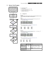
4.1 Display
Test
Purpose:
This test is used to check the driving circuits, the display and whether there are
any short-circuits, open-circuits or any other defects.
Player:
Following display patterns are used to test the display and its connections to
μ
P.
Pattern 1:
Default: All display control pins are ON
-
to check the open-circuits
Pattern 2:
Alternate display control pins are on (Test Pattern: 0x55)
-
to check the short-circuits on Data port
Receiver:
Following display patterns are used to test the display and its connections to
μ
P.
Pattern 1:
Default: All display control pins are ON
-
to check the open-circuits
Pattern 2:
Alternate display control pins are on (Test Pattern: 0x55)
-
to check the short-circuits on Data port
key
"
DisplayTest
"
triggered?
n
y
Activate and display
"
Pattern1
"
key
"
DisplayTest
"
triggered?
n
y
Activate and display
"
Pattern2
"
Main Menu
Display Test
key
"
"
triggered?
n
y
Summary of Contents for HTS5000W/12
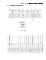
Page 15: ...EN 15 HTS5000W FTD Display Pin Connection 6 6 FTD Display Pin Connection ...
Page 16: ...EN 16 HTS5000W Notes 6 FTD Display Pin Connection ...
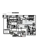
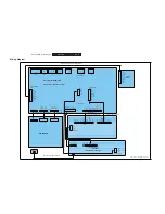
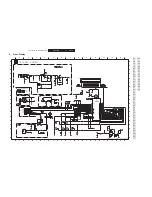
Page 40: ...EN 40 HTS5000W Notes Circuit Diagram and PWB Layout 8 ...
Page 60: ...EN 60 HTS5000W 9 Exploded View Module PWR 04 01 Non Wireless Notes ...

