EN 10
HTS5000W
4.
Dismantling Instructions & Service Positions
4.3
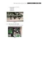
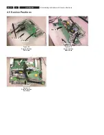
Dismantling of the Mono Board
1) Loosen 2 screws Pos 273 to remove the Transmitter
Board. (See Figure 3-3 & 3-4)
Figure 4-3
Figure 4-4
2) Loosen 1 screw Pos 260 to remove Tuner Module.
Figure 4-5
3) Loosen 4 screws Pos 257 as shown in Figure 3-6
Figure 4-6
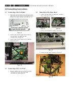
4. Dismantling Instructions
4.1
Dismantling of the PSU Board
1) The disc can be manually remove by inserting a minus
screw driver and push the lever in the direction as shown
in Figure 3-1 to unlock the tray and eject the disc out.
Figure 4-1
2) Loosen 5 screws Pos 272 to remove the Front Top.
- 1 screw each on the left and right side.
- 3 screws at the rear of the set.
3) Loosen 4 screws Pos 258 to remove PSU Board as
shown in Figure 3-2.
Figure 4-2
4.2
Dismantling of the Front Panel
1) Release 4 catches to remove the Front Panel Assy.
- 1 catch each on the left and the right side.
- 2 catches at the bottom of the set.
A
B
C
D
E
Summary of Contents for HTS5000W/12
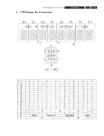
Page 15: ...EN 15 HTS5000W FTD Display Pin Connection 6 6 FTD Display Pin Connection ...
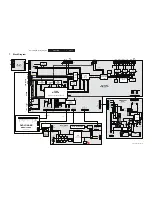
Page 16: ...EN 16 HTS5000W Notes 6 FTD Display Pin Connection ...
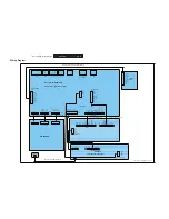
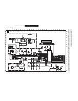
Page 40: ...EN 40 HTS5000W Notes Circuit Diagram and PWB Layout 8 ...
Page 60: ...EN 60 HTS5000W 9 Exploded View Module PWR 04 01 Non Wireless Notes ...

