EN 43
HTS5000W
9.
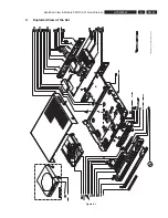
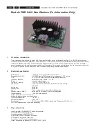
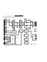
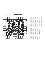
Exploded View & Module PWR 04-01 Non-Wireless
4
Introduction & de
fi
nitions
This
ampli
fi
er delivers 2 x 50 watts into 6 ohm loads. It is intended for a wireless surround system containing transmitter coupled to a
DVD main set and a so called receiver-ampli
fi
erunit.
Audiotransmission is purely digital and done on 2.4Ghz with “Polaris 2” TX and RX modules from Freesystems.
The
ampli
fi
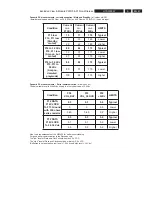
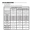
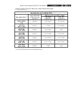
er powersupply combination can deliver continuously 1/8 of the 2 x 50 watts into 6 ohm loads. Regarding FTC rules: the
ampli
fi
er can deliver 1 x 50 Watts in left or right channel for 5 minutes ( only one channel driven) after a period of preheating for 1 hour
on 1/8 of 50 watts in each channel.
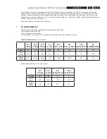
Full power: 50 Watts in 6 ohm = 17.3 Vrms
1/8 of full power : 6.25 Watts in 6 ohm = 6.12 Vrms
The
ampli
fi
er has a built in highpass
fi
lter ( around JRC 4560 opamp) and volumecontrol with M62429 chip from Renesas. One has
to use the by PSS developed tool to give the correct serial data to the volumechip, otherwise no testing is possible. (testtool 3104 137
00231)
Also, before connecting the ampli
fi
er to the power supply and applying inputsignals, be sure that the heatsink is mounted. (in all other
cases excessive temp-rise and thermal shutdown of the TDA8920TH is possible)
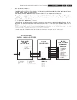
*** See below picture / schematic to have an idea how the
fi
nal receiverset is built up using ampli
fi
er 3104 137 0017
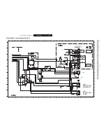
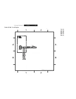
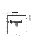
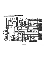
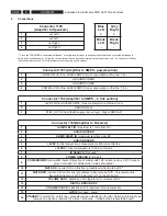
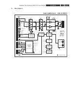
Connectiondiagram
Amplifier - receiver assy HTS5000
J1
Power supply
AC6632
3104 137 00181
J1: Mains input
1 = N
2= not connected
3 = L
1
J2
J3
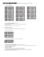
J2 to 1101: Power
1 = +27 Vdc
2 = Power Ground
3 = Power Ground
4 = -27 Vdc
J3 to 1102: 6Vdc
1 = + 6 Vdc
2 = GND 6 Vdc
3 = control (high = standby)
Amplifier
3104 137 00171
Receiver
3141 137 40090
Freesystems
1
1
1
Connector
1101
Connector
1102
16 fold to 1103
1 = AUDIO LEFT
2 = AUDIO GROUND
3 = AUDIO RIGHT
4 = AUDIO GROUND
5 = +6VDC
6 = +3 3VDC
7 = ID SEARCH
8 = POWER GROUND
9 = RX POWERDOWN
10 = MUTE RX
11 = MUTE DVD
12 = VOLUME DATA
13 = DIGITAL GROUND RX
14 = VOLUME CLOCK
15 = GPIO4
16 = STANDBY
1100:
speaker - out
Blue: left +
Black: left -
Grey: right +
Black: right -
1
16
1
16
Connector
1103
Summary of Contents for HTS5000W/12
Page 15: ...EN 15 HTS5000W FTD Display Pin Connection 6 6 FTD Display Pin Connection ...
Page 16: ...EN 16 HTS5000W Notes 6 FTD Display Pin Connection ...
Page 40: ...EN 40 HTS5000W Notes Circuit Diagram and PWB Layout 8 ...
Page 60: ...EN 60 HTS5000W 9 Exploded View Module PWR 04 01 Non Wireless Notes ...

