EN 50
HTS5000W
9.
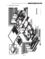
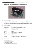
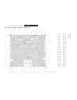
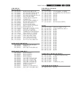
Exploded View & Module PWR 04-01 Non-Wireless
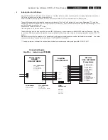
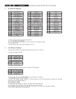
9 Connections
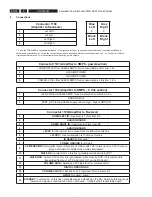
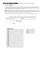
Connector 1100
(Ampli
fi
er to Speakers)
1
out Left +
2
out Left -
3
out Right –
4
out Right +
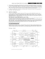
** Since the TDA 8920B is connected “antiphase” at its right and left input, the speakers should also be connected antiphase to
obtain good phase behavior. Follow the connections as above described. Note also that Right + and Left – on Connector 1100 are
interconnected to ground. This is important when measuring on this outputs
Connector 1101 (Ampli
fi
er to SMPS - powersection)
1
+POWER 27Vdc from AC6632 SMPS / max consumption on this line: 1.4 A
2
GROUND POWER
3
GROUND POWER
4
-POWER -27Vdc from AC6632 SMPS / max consumption on this line: 1.4 A
Connector 1102 (Ampli
fi
er to SMPS – 6 Vdc section)
1
+6VDC IN from AC6632 SMPS / max consumption on this line: 0.2 A
2
GROUND 6Vdc
3
STBY_OUT to the AC6632 supply / active high / High is SMPS off
Connector 1103(Ampli
fi
er to Receiver)
1
AUDIO LEFT IN
/ maximum is 1Vrms from RX
2
AUDIO GROUND
3
AUDIO RIGHT IN
/ maximum is 1Vrms from RX
4
AUDIO GROUND
5
+6VDC
for the receiver /max consumption is 200mA on this line
6
+3.3VDC
/ max consumption is 100mA on this line
7
ID SEARCH
/ Not used*
8
POWER GROUND
for RX part
9
POWERDOWN
from Ampli
fi
erboard / Detection of mains switch off / normal level is 3.2V / Pulse to
ground of minimum 15mSec when mains interrupted*
10
MUTE RX
/ normal 3.3V on this line / groundlevel when mute by RX*
11
MUTE DVD
/ normal 3.3V on this line / groundlevel when mute by DVD / This command is
transmitted from key1 at TX side to GPIO 1 on the RX board.
12
VOLUME DATA
/ dataline on 3V3 logic level for volumecontrol
13
DIGITAL GROUND RX
14
VOLUME CLOCK
/ clockline on 3V3 logic level for volumecontrol
15
GPIO4
Not used - spare*
16
STANDBY
/ normal 3.3V on this line / groundlevel when standby by the RX / Normally this line drops
low when no signal is received for a time > 4minutes. – timing by the Freesystems board*
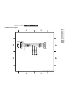
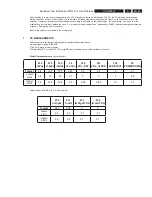
Blue
Left
+
Grey
Right
+
Black
Left
-
Black
Right
-
Summary of Contents for HTS5000W/12
Page 15: ...EN 15 HTS5000W FTD Display Pin Connection 6 6 FTD Display Pin Connection ...
Page 16: ...EN 16 HTS5000W Notes 6 FTD Display Pin Connection ...
Page 40: ...EN 40 HTS5000W Notes Circuit Diagram and PWB Layout 8 ...
Page 60: ...EN 60 HTS5000W 9 Exploded View Module PWR 04 01 Non Wireless Notes ...

