EN 45
HTS5000W
9.
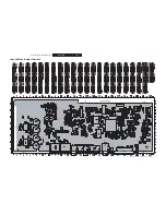
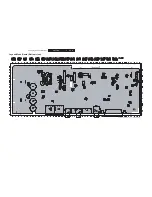
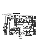
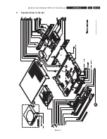
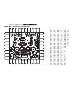
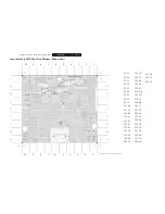
Exploded View & Module PWR 04-01 Non-Wireless
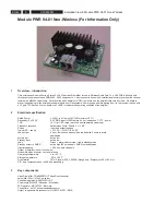
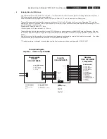
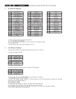
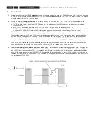
Best condition is to start every testsequence with F16 ( Standby) and also both Mutelines F10, F11 low. This gives a minimum load
startup condition. Initially, at
fi
rst startup, the volumechip will be on maximum attenuation (-80dB), so no sound will come out of the
ampli
fi
er. However, after disconnecting and again connecting the ampli
fi
er to the powersupply , the volumechip “can” be on the last
initial setting, but this is not always the case. So, it is best to load a certain “save” attenuation ( -50dB) towards the ampli
fi
er at startup.
( startup = amp muted and / or standby)
Be sure the heatsink is mounted in the correct way.
7 DC
MEASUREMENTS
Pcb connected to the testtool, all supplies connected as described above
No audioinput signals to the PCB.
F1 an F3 to ground ( Audio inputs)
F10 (standby), F11 (mute DVD), F16 (mute RX) low at startup by use of the switches on the tool
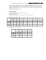
Static DC measurements.
( all values Vdc)
F32
+5Vdc
F35
+15Vdc
F36
-15Vdc
F6
+3.3Vdc
F34
VOL_DAT
F33
VOL_CLOCK
F29
6V DETECT
F9
POWERDOWN
Typical
5.4
15.7
-15.7
3.25
0.3
0.3
0
3.1
Lower
Limit
5.2
15
-15
3.1
0
0
0
2.9
Higher
Limit
5.6
16.4
-16.4
3.5
0.45
0.45
0.1
3.3
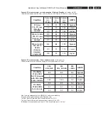
Values below valid if the +5 is 5.4 Vdc typical.
F30
In Right
F31
In Left
F37
IN Right TDA
F38
IN Left TDA
Typical
2.65
2.65
0
0
Lower
Limit
2.2
2.2
-0.1
-0.1
Higher
Limit
2.8
2.8
0.1
0.1
Summary of Contents for HTS5000W/12
Page 15: ...EN 15 HTS5000W FTD Display Pin Connection 6 6 FTD Display Pin Connection ...
Page 16: ...EN 16 HTS5000W Notes 6 FTD Display Pin Connection ...
Page 40: ...EN 40 HTS5000W Notes Circuit Diagram and PWB Layout 8 ...
Page 60: ...EN 60 HTS5000W 9 Exploded View Module PWR 04 01 Non Wireless Notes ...

