EN 52
HTS5000W
9.
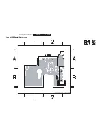
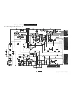
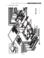
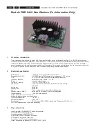
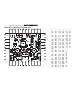
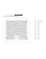
Exploded View & Module PWR 04-01 Non-Wireless
11 Mute
circuitry
1.
Normal operating condition or
PLAY mode:
the voltage on the “mode” pin of the ampli
fi
er TDA8920B will be 5Vdc. (level to be checked
on F39) This mainly due to the resistors R3125, R3122, R3110 and saturated transistors 7106, 7102). Transistor 7104 and 7101 are not
saturated at that moment. The green Led is on.
2.
Pulling the ampli
fi
er into
MUTE condition
can be mainly done by the command MUTE_RX, MUTE_DVD or the powerdown mute
circuitry around 7130 and 7103.
●
The RX module internally generates MUTE_RX when e.g. the
fi
eldstrenght of the 2.4Ghz carrier is too low or severe multipath
reception
occurs.
●
MUTE_DVD is a command generated by the DVD main unit e.g. mute button on the remote or volume “0”.
●
When the main /- 27Vdc drops below +/- 15V or when the 6Vdc supply drops below 4.5 V a fast mute command is produced
via diodes 6106 and / or 6101 towards 7104. (= this action happens when someone disconnect the unit from the mains)
All “Mute” commands initiate the same fast action via 7107 and 7104 towards the ampli
fi
er mode pin. Both main mute commands are
active low, and forces the level on the base of 7104 to 0.7Vdc, this results in a saturated 7104.
The powerdown transistors 7103 and 7130 are normally always saturated. At voltage drops, a fast positive level is applied via diodes
6106 and 6101 on the base of 7104, resulting in 2.5Vdc on the mode pin of the ampli
fi
er. This avoids plops in the surroundspeakers.
The resistors 3125 and 3121 de
fi
ne in this condition the level on the mode pin 6 of 7110 = TDA8920B: about 2.5Vdc. (level to be
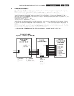
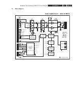
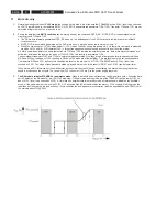
checked on F39). The slope of then transient between play and mute mode is the result of R3121 and C2185 (see below picture)
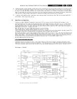
When muted, all DC references of the ampli
fi
er stay as they were; the class D keeps on oscillating, the status led stays green but no
sound is produced on the outputs. The control line (F22; connector 1102-pin 3) to the power supply stays low.
3.
The RX module initiates STANDBY or powersavemode.
When this module does not receive a valid signal for a time > 4minutes (time
set in Eeprom of the RX module), pin 16 of 1103 drops low, 7109 saturates and the mode pin of the TDA8920 is pulled low by 7101 to
about 0.15V. (level to be checked on F39). At this level the ampli
fi
erchip is in standbymode, all references are disabled, the oscillator
stops. At the same moment the level on STBY_OUT becomes high (6Vdc) and disables the main +/- 27Vdc supply. Also the green led
is switched off and the red led is switched on. In this condition the average power consumption (with the speci
fi
ed supply AC6632) out of
the mains is about 1W @ 230V
Summary of Contents for HTS5000W/12
Page 15: ...EN 15 HTS5000W FTD Display Pin Connection 6 6 FTD Display Pin Connection ...
Page 16: ...EN 16 HTS5000W Notes 6 FTD Display Pin Connection ...
Page 40: ...EN 40 HTS5000W Notes Circuit Diagram and PWB Layout 8 ...
Page 60: ...EN 60 HTS5000W 9 Exploded View Module PWR 04 01 Non Wireless Notes ...

