EN 46
HTS5000W
9.
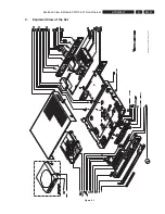
Exploded View & Module PWR 04-01 Non-Wireless
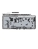
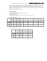
Dynamic DC measurements / Mute and Standby.
( all values Vdc)
Condition
F39
MODE
AMP
F28
MUTE
ALL
F22
STBY
OUT
F26
GREEN
LED
F27
RED
LED
F29
6V
DETECT
F9
POWER
DOWN
LIMITS
F16 low
F10, F11 low
(Standby,
muted)
0.25
3.2
6
4.22
0.1
0.1
3.1
Typical
0
2.9
5.7
3.8
0
Lower
0.4
3.5
6
4.5
0.3
Higher
F16 to 3.3Vdc
F10, F11 low
(Amp on, but
muted)
2.5
3.2
0.1
0.1
4.5
0.1
3.1
Typical
2.2
2.9
0
0
3.8
Lower
2.7
3.5
0.3
0.3
4.7
Higher
F16 to 3.3Vdc
F10, F11 to
3.3Vdc
(Amp on,
demuted,
playmode)
5
0.1
0.1
0.1
4.5
0.1
3.1
Typical
4.6
0
0
0
3.8
Lower
5.3
0.3
0.3
0.3
4.7
Higher
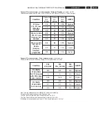
Condition:
Ampli
fi
er in
Play mode
Action: Switch
off the + 27v
dc supply
and check the
levels on F39
(MODE_AMP)
2.5
Typical
2.2
Lower
2.7
Higher
Condition:
Ampli
fi
er
powered
Action:
Connect F9
to ground F13
and check if a
puls appears
on F29
(this test to
be done on
samplebase)
Puls
0.7 Vdc
15mSec
0
Typical
Puls
0.7 Vdc
10mSec
0
Lower
Puls
0.7 Vdc
20mSec
0
Higher
Summary of Contents for HTS5000W/12
Page 15: ...EN 15 HTS5000W FTD Display Pin Connection 6 6 FTD Display Pin Connection ...
Page 16: ...EN 16 HTS5000W Notes 6 FTD Display Pin Connection ...
Page 40: ...EN 40 HTS5000W Notes Circuit Diagram and PWB Layout 8 ...
Page 60: ...EN 60 HTS5000W 9 Exploded View Module PWR 04 01 Non Wireless Notes ...

