EN 42
HTS5000W
9.
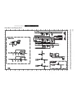
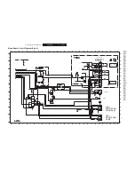
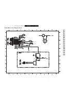
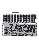
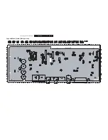
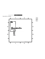
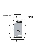
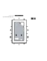
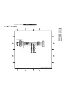
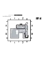
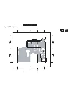
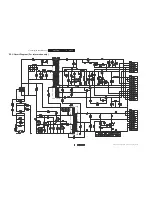
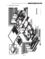
Exploded View & Module PWR 04-01 Non-Wireless
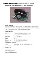
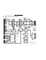
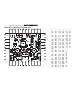
Module PWR 04-01 Non-Wireless (For Information Only)
1
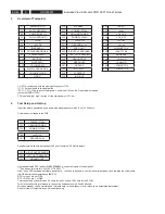
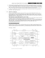
Overview - introduction
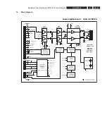
This wireless audio ampli
fi
er is a Stereo 2 x 50 Watt class D ampli
fi
er for use in Wireless Audio Sets. The FR4 PCB is build up with
through hole components and SMD 0603, 0805 components. Volumecontrol is done with a unidirectional serial signal from the receiver
towards the M62429 volumechip. A black extruded AL heatsink (4°C/W) is mounted on the ampli
fi
erchip with 2 screws. On board is
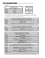
also all conditioning for the wireless receivermodule from Freesystems. Power supply and interfacing from / to the receiver is done with
a 16 pole FFC
fl
exlink. Also on board are 2 LEDS to indicate the operating condition of the ampli
fi
er.
2 Electrical
speci
fi
cation
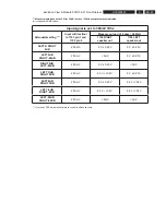
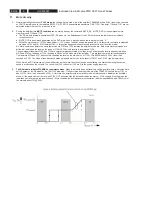
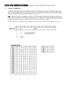
Rated Power
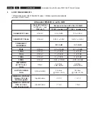
2 x 50W in 6 Ohm @ 10%THD maximum (FTC)
Sensitivity (2 x 50 W)
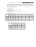
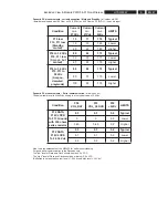
0.5 V RMS input for 50Watt into 6 ohm / see annex 1: FTC - power
THD
<0.1% at 1/8 P rated ( each channel separately measured)
Frequency
response
fl
at between 30Hz - 20kHz // +/- 1 dB
Phase
Input and output in phase
Typical DC – supply
+ 27 VDC / -27 VDC & 6VDC
Load output
6 ohm - Both channels should be loaded with 6 ohms to avoid
audioholes
Mute input
Active low
Standby input
Active low
Leds
Green = playmode or muted // red is standbymode
Standby output to SMPS
active high (6V unloaded) = SMPS in standbymode
Input impedance
< 20K ohm both channels
Output of ampli
fi
er is short circuit proof
No audible plops at power on or power down
Operating temperature:
0 to + 45 °C
Storage temperature
-25 to + 80 °C
Pcb material
FR4 / 2 layers / 0603, 0805 & through hole / Dimensions 90 x 100 mm
PB – free components and full pB free processing
3 Key
components
class D ampli
fi
er: TDA8920BTH / Philips Semiconductor
output
fi
lter: 22
μ
H / 470nF polyester
Conditioning preamp: NJM4560 / JRC
Volumechip: M62429 / Renesas – Mitsubishi
3V3 regulator: MC78FC33 / Motorola
Connectors : all JST except speakerconnector
Output to speakers: Easyconnector LQR3215-0102F / SMK
Summary of Contents for HTS5000W/12
Page 15: ...EN 15 HTS5000W FTD Display Pin Connection 6 6 FTD Display Pin Connection ...
Page 16: ...EN 16 HTS5000W Notes 6 FTD Display Pin Connection ...
Page 40: ...EN 40 HTS5000W Notes Circuit Diagram and PWB Layout 8 ...
Page 60: ...EN 60 HTS5000W 9 Exploded View Module PWR 04 01 Non Wireless Notes ...

