3 • Bridged data application
Models 3224 G.SHDSL IpDSLAM & 6081RC NAS Applications Guide
30
Interface configuration
7. Configure LCP options as needed or accept the default settings. Do not configure IP and IPCP options.
8. Click on the
Submit
button to save changes.
9. Repeat the PPP channel configuration steps 1 through 7 for other channels as needed.
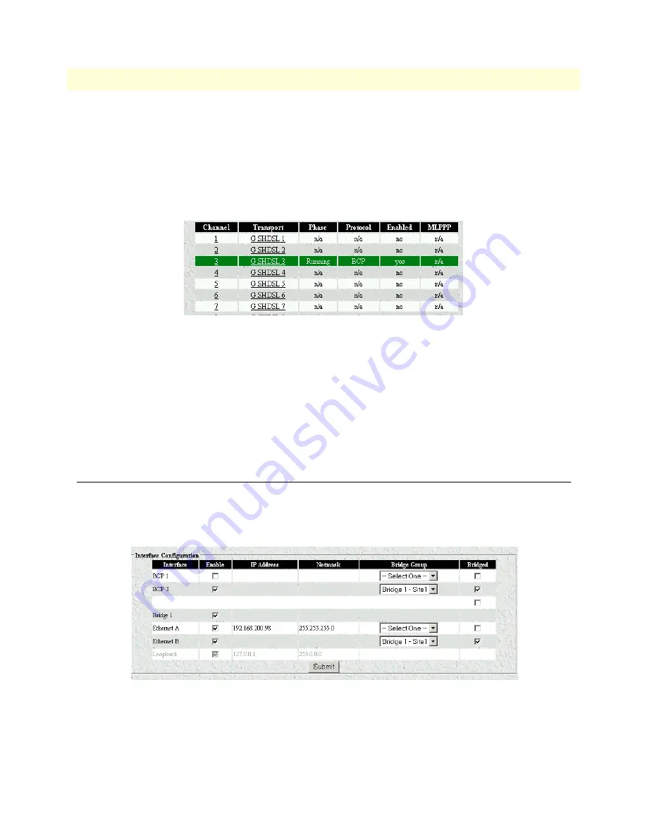
Once all parameters have been configured, the PPP Status page should display the information shown in
figure 26
.
Figure 26. PPP Status page
At this point the 3224 or 6081RC will start negotiating PPP/BCP connections with a remote peer. The
Status window will turn yellow, indicating that negotiation is in progress.
10. Attach a defined bridge to an Ethernet port, so that traffic bridged from the remote CPEs is forwarded to
the LAN attached to the 3224 or 6081RC.
Note
Bridge 1 can be attached to any physical interface including back-
plane Ethernet ports or other H.110 ports.
Interface configuration
The
Interface Configuration
page (see
figure 27
) displays all interfaces (physical and logical) previously defined.
In this example, PPP interface BCP 3 (channel 3) and corresponding bridge Bridge 1 - site1, Ethernet A, Ether-
net B, and a Loopback interface (default) are shown.
Figure 27. Interface Configuration Page
To activate a bridged link from customer sites (BCP) between the remote CPEs and the 3224 or 6081RC
bridge, do the following:


