background image

7 • Verifying operation

Models 3224 G.SHDSL IpDSLAM & 6081RC NAS Applications Guide

54

Introduction

Introduction

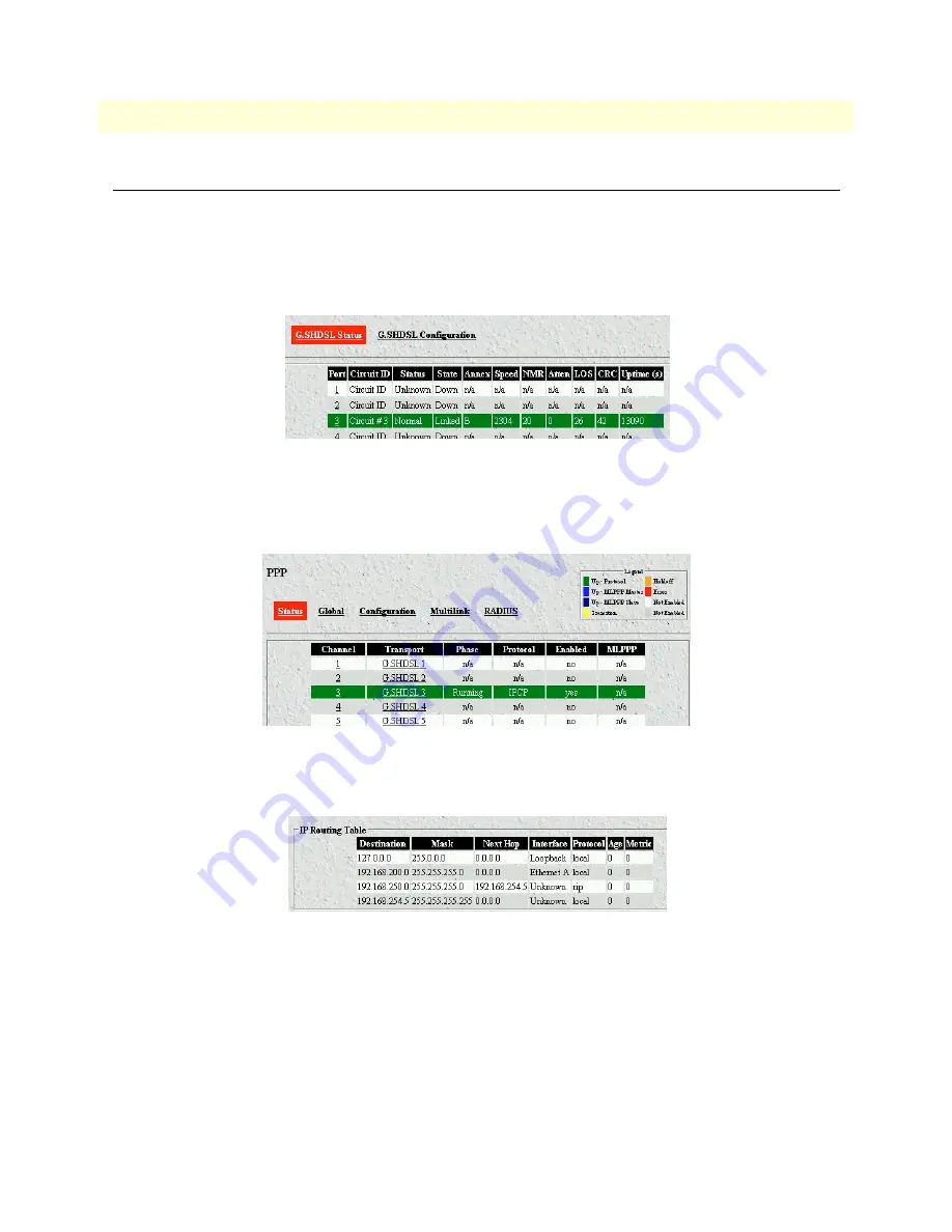
Before any testing can be performed, verify operation of the DSL(3224 only), PPP, and routing modules. To 
verify the operation of the 3201 and 3224/6081RC in this application, go to the 3224 configuration pages. 

1. For the 3224, click on the G.SHDSL link in the 

Configuration Menu

 pane and verify that DSL port 3 is 

up and linked to the remote unit (shown in green in 

figure 48

).

Figure 48. G.SHDSL Status page

2. Click on the PPP link in the 

Configuration Menu

 pane, and verify that PPP channel 3 is up an running 

(shown in green in 

figure 49

)

Figure 49. PPP Status Page

3. Click on the 3224/6081RC Routing – Static link in the 

Configuration Menu

 pane to verify routes.

Figure 50. IP Routing table

Summary of Contents for ForeFront 6081RC EdgeRoute

Page 1: ...6081RC EdgeRoute Network Access Server Applications Guide Sales Office 1 301 975 1000 Technical Support 1 301 975 1007 E mail support patton com WWW www patton com Document Number 11002U5 001 Rev B Pa...

Page 2: ...Patton Electronics Company in the United States and other countries Copyright Copyright 2004 Patton Electronics Company All rights reserved Notice The information in this document is subject to chang...

Page 3: ...configuration 22 Initiating bridged Ethernet data communications 22 Modifying the factory default configuration 22 Logging in using the factory default IP address 23 Modifying the IP address for Ether...

Page 4: ...tion 45 General 45 RIP timers 46 6 Configuring the remote site router Model 3201 47 Introduction 48 Ethernet port IP address configuration 48 G SHDSL layer configuration 48 PPP layer configuration 48...

Page 5: ...e IpDSLAM and Network Access Server for a bridged data application Chapter 4 describes configuring the IpDSLAM and Network Access Server for a VLAN bridged connection application Chapter 5 describes c...

Page 6: ...em would display them dir Bold Courier font indicates where the operator must type a response or command Table 2 Mouse conventions Convention Meaning Left mouse button This button refers to the primar...

Page 7: ...5 Chapter 1 Introduction Chapter contents Overview 6...

Page 8: ...ite and routes bridges DSL subscribers data when used in conjunction with Patton s model 3096RC 16 port G SHDSL TDAC and or 3196RC 16 port iDSL T DACS The Models 3224 IpDSLAM and 6081RC EdgeRoute Netw...

Page 9: ...3224 G SHDSL IpDSLAM 6081RC NAS Applications Guide 1 Introduction Figure 3 shows the factors that should be considered when configuring bridged or routed operation Figure 3 Bridged and routed configu...

Page 10: ...1 Introduction Models 3224 G SHDSL IpDSLAM 6081RC NAS Applications Guide 8 Overview...

Page 11: ...tion Chapter contents Introduction 10 Physical layer characteristics 10 Configuring Model 3224 G SHDSL parameters 11 Configuring Model 6081RC H 110 parameters 12 Defining H 110 channels 13 Defining H...

Page 12: ...096RC 3196RC 2616RC or 6511RC via a mid plane H 110 bus In G SHDSL applications DSL frames carrying data from customer sites are terminated at the ForeFront chassis by a Model 3096RC data is then pass...

Page 13: ...ge in the configuration menu pane click the G SHDSL G SHDSL Configuration hyperlink The G SHDSL status and configuration pages see figure 5 will appear on your screen Figure 5 G SHDSL Configuration pa...

Page 14: ...s partitioned into 32 ports Each H 110 port can handle up to 128 timeslots each timeslot is 64 kbps H 110 timeslots are unidirectional for a full duplex link timeslots need to be defined for each dire...

Page 15: ...ered Note If you want to delete a channel configuration from the listing click the Delete check box for the channel you want removed then click the Delete Channel s button Note If a bridged or routed...

Page 16: ...to 32 in the Port text box 2 Enter the Starting Timeslot each H 110 port can handle up to 128 slots for example if timeslots 1 16 will be used enter 1 in this text box 3 Enter the length of the channe...

Page 17: ...ou want to delete a map configuration from the listing click the Delete check box for the map you want removed then click the Delete Map s button Once both maps for a channel have been entered the H 1...

Page 18: ...2 Physical layer configuration Models 3224 G SHDSL IpDSLAM 6081RC NAS Applications Guide 16 Configuring Model 6081RC H 110 parameters...

Page 19: ...ications 22 Modifying the factory default configuration 22 Logging in using the factory default IP address 23 Modifying the IP address for Ethernet interface A optional 25 Creating a bridge group 26 P...

Page 20: ...protocol PPP for data delivery across the G SHDSL links by encapsulating each BCP datagram in a PPP frame Figure 11 Model 3324 bridged data application diagram In general network engineers may find th...

Page 21: ...Introduction 19 Models 3224 G SHDSL IpDSLAM 6081RC NAS Applications Guide 3 Bridged data application Figure 12 Model 6081RC bridged data application diagram...

Page 22: ...Network Access Server Ethernet Interface A You will use the management workstation on Interface A to configure the IpDSLAM or EdgeRoute Net work Access Server using a web browser Figure 13 Port conne...

Page 23: ...nel of the unit Units not equipped with a PMC card have both Ethernet ports B and C internally connected to the ForeFront Chassis midplane It s possible to use the model 6081RC Ethernet port A simulta...

Page 24: ...ny Model 3201 used in this network is factory con figured in CO mode you must re configure the device for CP mode For more information on configuring the Model 3201 refer to the Model 3201 Getting Sta...

Page 25: ...8 That is the first three octets or your workstation s IP address must be 198 168 200 Using a workstation connected to the IpDSLAM s Ethernet Interface A do the following 1 Power up the workstation an...

Page 26: ...e or at different times using multiple workstations on the LAN Before connecting Ethernet Port A to the LAN you must first assign an IP address to Ethernet Port A that has the same network number as t...

Page 27: ...thernet port A Disconnect your workstation and connect Inter face A to the Ethernet LAN you can then log in to the management interface from a workstation connected to the LAN using a web browser and...

Page 28: ...guration page see figure 21 This page provides several buttons for navigating through stored bridge configuration The Refresh Page button forces the 3224 or 6081RC to display changes made since the pr...

Page 29: ...cal priority value is elected as the spanning tree root switch which is the logical center of the spanning tree topology in a switched network If all switches are configured with the default priority...

Page 30: ...PPP channel status information in addition it offer links for global multilink and radius configuration pages There are two ways to access a PPP channel configuration page by clicking on the channel...

Page 31: ...nges made to a port configuration Figure 25 PPP Options page 3 Under the heading PPP Options select one of the following network control protocols NCP from the Mode menu BCP bridge control protocol IP...

Page 32: ...Status window will turn yellow indicating that negotiation is in progress 10 Attach a defined bridge to an Ethernet port so that traffic bridged from the remote CPEs is forwarded to the LAN attached t...

Page 33: ...B row locate the drop down menu under Bridge Group see figure 27 on page 30 select Bridge 1 Site1 3 Place a checkmark under the bridged column to enable bridged data to Ethernet B 4 Click on the Subm...

Page 34: ...the operation of the 3201 and 3224 6081RC in this application go to the 3224 configuration pages To view the G SHDSL ports on the Model 3224 click on the G SHDSL link on the Configuration menu pane V...

Page 35: ...f a PC or terminal at the remote site uses IP address 192 168 200 20 enter the following com mand at the PC attached to the model 3201 ping 192 168 200 20 the remote computer should respond with a pin...

Page 36: ...3 Bridged data application Models 3224 G SHDSL IpDSLAM 6081RC NAS Applications Guide 34 Verifying operation...

Page 37: ...35 Chapter 4 VLAN bridged connection Chapter contents Introduction 36 Attaching a VLAN ID to an Ethernet interface 36 Attaching a bridge interface to a VLAN module 37...

Page 38: ...sion to the remote CPE To create VLAN connections do the following 1 On the model 3224 Configure G SHDSL Channels see section Configuring Model 3224 G SHDSL parameters on page 11 for details On the Mo...

Page 39: ...a bridge interface to a VLAN module Once the desired VLAN has been created it is necessary to attach it to a bridge group as follows 1 Click the Interface link in the Configuration Menu pane see figu...

Page 40: ...4 VLAN bridged connection Models 3224 G SHDSL IpDSLAM 6081RC NAS Applications Guide 38 Attaching a bridge interface to a VLAN module...

Page 41: ...onfiguration 41 Configuring G SHDSL parameters 3224 only 41 Configuring H 110 ports 6081RC only 41 PPP global and channel configuration 41 Global configuration 41 PPP channel configuration 43 PPP opti...

Page 42: ...t network than the 3201s at remote locations Customer data at remote locations is routed by the corresponding 3201 and sent via the DSL link to the cen tral location The central site model 3224 6081RC...

Page 43: ...only See section Configuring Model 3224 G SHDSL parameters on page 11 Configuring H 110 ports 6081RC only See section Configuring Model 6081RC H 110 parameters on page 12 PPP global and channel confi...

Page 44: ...rab two consecutive addresses beginning at 192 168 254 0 from this pool for each PPP channel connection one for the local PPP inter face and one for the remote PPP interface 4 Leave all other settings...

Page 45: ...Enabled option This window also offers the option for passive or active PPP Leave the Passive box unchecked active PPP mode to allow the 3224 to immediately start sending PPP configuration frames to t...

Page 46: ...e 3224 from the IP global pool 2 Remote IP Address Use default IP address assigned by the 3224 6081RC from the IP global pool 3 Peer Proxy ARP Check this option to allow the 3224 6081RC to respond to...

Page 47: ...ion 1 Click on the Routing RIP menu option in the Configuration Menu pane to display the Routing RIP con figuration page See figure 41 2 The RIP page allows configuring options for General global and...

Page 48: ...ute If 180 seconds have passed since the last time the time out was initialized the route is considered to have expired and route deletion process is started Garbage Collection Use default of 120 seco...

Page 49: ...pter 6 Configuring the remote site router Model 3201 Chapter contents Introduction 48 Ethernet port IP address configuration 48 G SHDSL layer configuration 48 PPP layer configuration 48 RIP configurat...

Page 50: ...l 3201 User Guide for more information G SHDSL layer configuration The 3201 ships from the factory set to operate in Remote slave mode while the 3224 and 6081RC operate always in Central mode master i...

Page 51: ...and description for the routed link Figure 43 WAN Connection Options page 4 Click on Edit PPP to edit the PPP link options Some fields will be filled by values negotiated by this router and the 3224 6...

Page 52: ...d look at the Connect State field 6 Click on the Edit IP interface link to verify the 3201 has obtained a WAN IP address from the 3224 6081RC Leave all options in their default state Figure 45 Edit IP...

Page 53: ...Configuration page 5 At the Route Configuration page enter Destination Gateway and Netmask information as shown above 6 Click on the Update button Note The Gateway address in the example above points...

Page 54: ...6 Configuring the remote site router Model 3201 Models 3224 G SHDSL IpDSLAM 6081RC NAS Appli 52 PPP layer configuration...

Page 55: ...53 Chapter 7 Verifying operation Chapter contents Introduction 54 Verifying routed connection 55...

Page 56: ...4 configuration pages 1 For the 3224 click on the G SHDSL link in the Configuration Menu pane and verify that DSL port 3 is up and linked to the remote unit shown in green in figure 48 Figure 48 G SHD...

Page 57: ...terminal at the customer site to ping a PC or termi nal attached to the LAN port Ethernet A of the Model 3224 6081RC For example if the PC or terminal at the remote site uses IP address 192 168 200 2...

Page 58: ...7 Verifying operation Models 3224 G SHDSL IpDSLAM 6081RC NAS Applications Guide 56 Introduction...

Page 59: ...r contents Introduction 58 Contact information 58 Warranty Service and Returned Merchandise Authorizations RMAs 58 Warranty coverage 58 Out of warranty service 58 Returns for credit 58 Return for cred...

Page 60: ...cts are carefully tested before ship ment All of our products are backed by a comprehensive warranty program Note If you purchased your equipment from a Patton Electronics reseller ask your reseller h...

Page 61: ...Completing a request on the RMA Request page in the Support section at www patton com By calling 1 301 975 1000 and speaking to a Technical Support Engineer By sending an e mail to returns patton com...

Page 62: ...8 Contacting Patton for assistance Models 3224 G SHDSL IpDSLAM 6081RC NAS Applications Guide 60 Warranty Service and Returned Merchandise Authorizations RMAs...

Reviews: