background image

3

TIP OVER HAZARD

The SFC dust collector should be mounted on a solid, 

level, reinforced concrete foundation. Other mounting 

options are also possible. Structural calculations for  

the foundation or other mounting arrangements  

must include the weight of the collected material  

and  the  weight of all auxiliary equipment installed  

with  the dust collector (ducting,  abrasive inlet,  

blower package, afterfilter assembly, etc.). These 

weights must be considered together with wind 

loading, seismic loading and other live load ratings 

when designing the dust collector foundation sup-

port structure. Consult a professional engineer when 

designing the foundation for the unit.

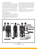
The system should be designed with the ability to regulate airflow. 
Two common ways to do this are through the use of flow/volume 
control dampers or variable frequency drives to control the speed 
of the fan motor.  Parker offers both of these options. If flow con-
trol dampers are selected, the interconnecting duct work should 
be designed to account for the installation of said damper. These 
dampers can be installed on the inlet or outlet ducting of the SFC 
unit. Whether you control the flow through the use of a damper 
or VFD, the ductwork must be properly sized to meet the recom-
mended air velocities for the material being collected.
Follow ducting design methods as listed in the Industrial Ventilation 
Manual as recommended by the American Conference of 
Governmental Industrial Hygienists.

3.3  Assembly Of Standard Equation

CRUSH AND ELECTROCUTION HAZARD

Use adequate safety measures when lifting and 
assembling any heavy components. Consult your 
plant safety personnel for recommendations.
 In preparing to attach the filter module to the hopper,  
connect lifting slings and spreader bars to all filter 
module lifting lugs with clevis pins. Use spreader 
bars to distribute the load evenly. Location must 
be clear of all obstructions, such as utility lines or roof 
overhangs.

Remove all crating, strapping and hold-down bolts. Locate all 
hardware bags, sealant and other assembly materials provided 
with your unit.

3.  Installation

3.1  Off Loading and Inspection

SFC dust collector modules are shipped assembled (with car-
tridges installed) on skid(s). Other skids will contain the hopper/
leg assembly and other components. Other accessories (afterfilter 
assemblies, blower packages, dust storage drums, silencers, 
etc.) may be on additional, separate skids.

TIP OVER HAZARD

  Lift the dust collector components by the packing skids 

or use the external lifting lugs provided on the filter 
module. Do not lift the filter module of the dust collec-
tor by placing lift truck forks through the cartridge filter 
access doors. The filter support rails or venturi installed 
on the tubesheet could be damaged.

Upon receipt of your unit, check for any shipping damage.  
A damaged carton indicates that the equipment may have 
received rough handling during shipping that may have caused pos-
sible internal damage. Notify your delivery carrier and enter a claim 
if any damage is found.

3.2  Installation Planning

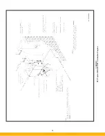
The proper location of your dust collection equipment is very 
important. Refer to Figures 2 and 3 for typical installation details.
Certain items should be considered when locating the unit, such 
as emptying of the dust storage drum(s), filter removal require-
ments, compressed air connections, access to the clean air 
plenum, electrical connections, blower location and discharge 
direction. The shortest duct length with a minimum number of 
elbows will maximize the performance of the unit. Ease of main-
tenance should also be considered when selecting the location 
and orientation of the system. Refer to Figure 3 for recommended 
clearances.

EXPLOSION HAZARD


In the case of spark producing processes, system 
design should incorporate measures to prevent live 
sparks from entering the dust collector. Consult local 
authorities for the location of the unit and any additional 
precautions to consider when collecting combustible, 
explosive or hazardous dusts. General warnings and 
cautions are provided on page iii and in Section 1.


!

  D A N G E R


!

  D A N G E R


!

  D A N G E R


!

  D A N G E R

Summary of Contents for SFC

Page 1: ...Downward Flow Cartridge Dust Collector Owner s Manual Model SFC...

Page 2: ...Parker Parker Order _________________________________________________________________ Unit Model ___________________________________________________________________ Unit Serial ______________________...

Page 3: ...odule Sections applies to 4 or more modules 6 3 4 Electrical Installation 11 3 4 1 Mounting the Controls 11 3 4 2 Solenoid Valve Enclosure Wiring 11 3 4 3 Heater Wiring 15 3 5 Compressed Air Connectio...

Page 4: ...Dust Removal 24 5 3 Servicing the Compressed Air Components 24 5 4 Servicing the Direct Drive Blower and Motor System 24 5 5 Servicing Cartridge Media 25 5 6 Servicing Optional Return Air Safety Filt...

Page 5: ...t collector The unit should be inspected frequently and dirt removed to prevent excessive accumulation which may result in flash over or fire damage The SFC system should not be used to support person...

Page 6: ...nt should be by a licensed contractor that is also experienced in potential fire and explosion hazards and adheres to related local state and federal codes standards laws and regulations Parker is not...

Page 7: ...v Page intentionally left blank...

Page 8: ...ding in non traffic areas even though the dust collector is equipped with an explosion vent 2 Introduction Thank you for selecting Parker dust collection equipment to assist you in your commitment to...

Page 9: ...nism provides brief bursts of compressed air directed through the diaphragm valves toward the cartridge filter This pulsing action dislodges the collected particles from the media where they fall into...

Page 10: ...crating strapping and hold down bolts Locate all hardware bags sealant and other assembly materials provided with your unit 3 Installation 3 1 Off Loading and Inspection SFC dust collector modules are...

Page 11: ...4 FIGURE 2 SFC Typical SINGLE UNIT Installation Diagram PARKER PARKER 44 10335 0001...

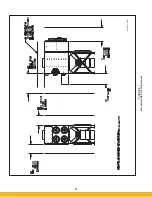
Page 12: ...5 FIGURE 3 Recommended Unit Clearances 44 10337 0001...

Page 13: ...hopper and filter module together Securely tighten all hardware at the filter module and hopper Recheck leg assembly sway braces to ensure they are tight Install fasteners bolt flat washer lock washer...

Page 14: ...7 FIGURE 4 Single Hopper SFC 44 10309 0001...

Page 15: ...8 FIGURE 5 Multiple Hopper SFC 44 10309 0002...

Page 16: ...9 FIGURE 6 Multiple Hopper SFC 44 10309 0003...

Page 17: ...10 FIGURE 7 Multiple Modules SFC 44 10310 0001...

Page 18: ...pulse cleaning Motor starter with Digital Pulse Control DPC for on demand pulse cleaning VFD with DPM for continuous pulse cleaning VFD with DPC for on demand pulse cleaning Refer to Parker sales orde...

Page 19: ...12 FIGURE 8 SFC Pressure Gauge Installation 44 10333 0001 Rev A...

Page 20: ...13 FIGURE 9 Solenoid Wiring to Pulse Controls for 2 3 4 and 5 Tier Units...

Page 21: ...14 FIGURE 10 Pneumatic Valve Assembly 44 10332 0001...

Page 22: ...l compressed air supply pipe fittings and connections 3 6 Assembly of Optional Equipment 3 6 1 Blower Purge Package Installation TIP OVER HAZARD Anchor dust collector to concrete pad prior to install...

Page 23: ...16 FIGURE 11 Legs Support Top Mount Blower 44 10331 0001 NOTE FOR BLOWERS 20 HP OR LARGER SUPPORT LEGS ARE REQUIRED TO BE INSTALLED UNDER THE CLEAN AIR PLENUM...

Page 24: ...17 FIGURE 12 Abrasive Inlet Installation 44 10338 0001...

Page 25: ...ry air lock Do not allow any object to be placed in or near the rotary air lock during operation Verify rotary air lock rotation matches rotation arrows affixed to assembly 3 6 4 Abrasive Inlet Instal...

Page 26: ...s not designed for dust storage The slide gate should remain open during normal operation 3 6 6 Inlet Cover and Blank Cover Plate Installation Inlet collar and blank cover plates bolt directly to the...

Page 27: ...20 FIGURE 16 EDAP Interconnection FIGURE 15 EDAP Installation 48 10007...

Page 28: ...transport an assembled 5 high unit due to height restrictions within the vehicle When shipping this unit it will be necessary to ship the EDAP separately This will require the customer to assemble th...

Page 29: ...interchange at motor junction box Engage starter disconnect switch start blower and recheck rotation NOTE Proper blower rotation is required to move the designed amount of air A blower rotating in the...

Page 30: ...23 FIGURE 17 SFC Series Door Filter Installation 44 10329 0001...

Page 31: ...timerboard to the Continuous Clean position Or if the system is sup plied with DPC Pulse Control place the Continuous Clean PS switch on the timerboard to PS position The MOT AUX terminals at the time...

Page 32: ...ace prior to being closed A flat solid section of door handle will be visible when door assembly is in the properly closed position Refer to Figure 17 If cam surface of the door handle is visible Quic...

Page 33: ...for HEPA filters TABLE 2 Cartridge Filters CARTRIDGE FILTER PARKER PART NUMBER GENERAL DESCRIPTION OF FILTER MEDIA ProTura Nanofiber 33 10089 ProTura Nanofiber layer on cellulose ProTura Nanofiber FR...

Page 34: ...l This may require bending panel sections away from the frame for frame removal Care should be taken to avoid sharp panel edges during this activity 4 Dispose of the removed rupture panel in accordanc...

Page 35: ...proper motor starter overload rating against full load amps on motor name plate Adjust or replace overloads as required Ensure drum is properly sealed against drum lid package Ensure drum lid package...

Page 36: ...ge to the timer board and voltage output from timer boards to solenoid valves Consult DPM DPC Pulse Control Panel Installation and Operation Manual for additional assistance Reduce high set point on D...

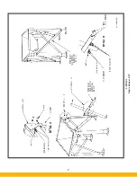
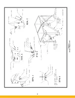
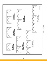
Page 37: ...30 7 Illustrated Parts FIGURE 21 SFC Series 44 10330 0001 FIGURE 22 SFC Series Explosion Vents...

Page 38: ...0020 20 Gallon Drum Lid 9 45 10022 0055 55 Gallon Quick Release Collar 9A 45 10022 0020 20 Gallon Drum Quick Release Collar 10 15 0233 14 Hose Clamp 11 15 0202 14 Flexible Duct 12 18 0944 14 Adapter...

Page 39: ...32 Page intentionally left blank...

Page 40: ...or misuse misapplication or normal wear and tear e Equipment not properly installed operated and maintained under normal conditions and recommended applications As Buyers exclusive remedy for any def...

Page 41: ...shooting effort details 5 Description of physical location and or environment details The Buyer shall cooperate with PARKER in its investigation and provide full information and documentation concerni...

Page 42: ...arker com dhfns Hiross Zander Essen Germany 49 2054 9340 www parker com hzfd Padova Italy 39 049 9712 111 www parker com hzfd Engine Filtration Water Purification Racor Dewsbury England 44 0 1924 487...

Reviews: