


iv
COMBUSTIBLE DUST HAZARDS –
SMOG-HOG
®
and DUST-HOG
®
Pollution Control Systems
Pursuant to National Fire Protection Agency (NFPA) Standards, the owner/user is required to test their dust mixtures
to evaluate and understand potential combustion or deflagration hazards that may exist. In addition, NFPA standards
require the owner/user to perform and have record of a Dust Hazard Analysis (DHA) if there is potentially a combustible
material involved within or exposed to the process.
The DHA serves as a systematic review of the process to:
1) Identify where fires and explosions can occur;
2) Identify the potential causes and consequences, and;
3) Determine if existing and proposed safeguards are sufficient.
It is the responsibility of the owner/user to evaluate, interpret and document any associated risk in their process
including adherence and compliance to any and all applicable local, state and federal codes, standards, laws and
regulations.
It is the sole responsibility of the equipment owner/user of record to coordinate and perform sample material collection
and combustion/explosivity testing of any and all dust and material that will be extracted and filtered by the Air Pollution
Control (APC) filtration equipment and to notify Parker of the results prior to any discussion involving equipment
specification and solution recommendation. It is recommended to utilize a Certified Industrial Hygienist (CIH) or certified
safety expert that is properly trained, licensed and approved and to use a licensed and approved dust testing facility
for proper dust and material analysis, testing protocol and reporting procedures. A sample of testing facilities and list of
Industrial Hygiene (CIH) and other occupational and environmental health and safety (OEHS) consultants can be located
through AIHA (American Industrial Hygiene Association) website.
To minimize the risk of fire or explosion, user must ensure proper installation, operation and maintenance of Parker
equipment. Since application, installation, operation and maintenance are beyond the control of Parker, Parker disclaims
any liability or responsibility for damage from fires or explosions regardless of origin. Parker recommends that all APC
dust collection equipment, installation and application conform to any and all applicable local, state and federal
standards, codes, laws and regulations including the addition of appropriate fire or explosion protection systems
including but not limited to venting, mitigation, suppression and isolation when and where required. Installation of
Parker equipment should be by a licensed contractor that is also experienced in potential fire and explosion hazards
and adheres to related local, state and federal codes, standards, laws and regulations. Parker is not an expert nor
certified design consultant in relation to spark, fire or explosion mitigation including but not limited to detection,
mitigation, suppression and isolation pf combustible dusts and materials. Therefore, Parker recommends that any
industrial air filtration system recommendation, design or solution be reviewed, approved, stamped and signed by
an industry expert consultant in air filtration systems, combustible dust/materials or certified safety expert such as a
Certified Industrial Hygienist (CIH) or a Certified Professional Engineer (PE) who is a licensed and certified expert with
industrial filtration system design and application including adherence and compliance to any and all applicable local,
state and federal codes, standards, laws and regulations.
If requested and ordered by the Buyer or owner/user and approved by Parker IOU engineering, sprinkler connection
couplers may be supplied and factory installed with certain DustHog dust collector models such as the MCB, SDC, and
SFC. The buyer or owner/user is responsible to supply, install and test the sprinkler head and any related or required fire
control system devices, components or accessories. It is the responsibility of the buyer or owner/user to test functionality
and operation of the fire control system including but not limited to correct water pressure, water leakage, correct
installation, appropriate fire control system component location, correct operation and appropriate application while
strictly adhering to any and all prescribed AHJ, OSHA, NFPA, Federal, State/Provincial and Local codes, standards,
regulations and instructions applicable to industrial dust collectors, fire control systems and any related or required
components and processes.
Pursuant to Parker’s Offer of Sale (terms and conditions) and by accepting the purchased equipment, Buyer and owner/
user agree to defend, indemnify, and hold harmless Parker, its successors, assignees, suppliers, shareholders, directors,
officers, employees, agents, and affiliated companies from all losses, costs, damages, demands, claims, liabilities, fines,
penalties or any other expenses (including attorneys’ fees, court costs, and expert fees) (collectively “losses”), caused or
contributed to in any way by Buyer or owner/user’s failure to follow these instructions and/or failure to properly install,
apply, operate, or maintain the equipment purchased from or supplied by Parker, or losses caused or contributed to in
any way by Buyer’s and owner/user’s failure to provide accurate information, specifications or dust explosivity values.
Summary of Contents for SFC
Page 1: ...Downward Flow Cartridge Dust Collector Owner s Manual Model SFC...
Page 7: ...v Page intentionally left blank...
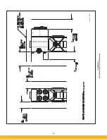
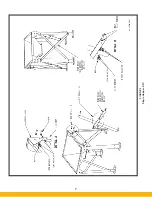
Page 11: ...4 FIGURE 2 SFC Typical SINGLE UNIT Installation Diagram PARKER PARKER 44 10335 0001...
Page 12: ...5 FIGURE 3 Recommended Unit Clearances 44 10337 0001...
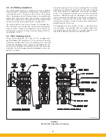
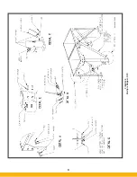
Page 14: ...7 FIGURE 4 Single Hopper SFC 44 10309 0001...
Page 15: ...8 FIGURE 5 Multiple Hopper SFC 44 10309 0002...
Page 16: ...9 FIGURE 6 Multiple Hopper SFC 44 10309 0003...
Page 17: ...10 FIGURE 7 Multiple Modules SFC 44 10310 0001...
Page 19: ...12 FIGURE 8 SFC Pressure Gauge Installation 44 10333 0001 Rev A...
Page 20: ...13 FIGURE 9 Solenoid Wiring to Pulse Controls for 2 3 4 and 5 Tier Units...
Page 21: ...14 FIGURE 10 Pneumatic Valve Assembly 44 10332 0001...
Page 24: ...17 FIGURE 12 Abrasive Inlet Installation 44 10338 0001...
Page 27: ...20 FIGURE 16 EDAP Interconnection FIGURE 15 EDAP Installation 48 10007...
Page 30: ...23 FIGURE 17 SFC Series Door Filter Installation 44 10329 0001...
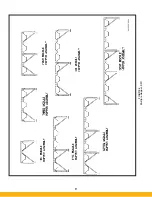
Page 37: ...30 7 Illustrated Parts FIGURE 21 SFC Series 44 10330 0001 FIGURE 22 SFC Series Explosion Vents...


