


1
1. Important Notice
This manual contains important safety information and pre-
cautionary measures. It is impossible to list all potential hazards
associated with every dust collection system in each application.
Proper use of the equipment should be discussed with Parker
Hannifin. Operating personnel should be aware of, and adhere
to, the most stringent safety procedures.
EXPLOSION HAZARD
• Avoid mixing combustible materials such as alumi-
num, paper, wood or other organic dusts with dusts
generated from grinding materials. A fire hazard could
develop from sparks entering the dust collector.
When collecting flammable or explosive materials,
the dust collector should be located outdoors and
incorporate the appropriate safety measures and/or
accessories.
•
When collecting emissions from spark-producing
processes, care must be taken to reduce any poten-
tial fire hazards. System design should include
methods to prevent sparks from entering the dust
collector. Dust collectors do not contain fire extin-
guishing equipment unless specifically ordered.
Experts in the field of fire extinguishing equipment
should be consulted for recommendations concern-
ing proper fire detection and suppression systems.
•
Some dust collection systems require explo-
sion venting. Consult your insurance underwriter,
NFPA (National Fire Protection Association) man-
ual and your local fire authorities to determine the
requirements for explosion venting.
• Be careful and conscientious – consult national and
local fire codes, waste disposal, safety and other
appropriate authorities. Comply with their recom-
mendations for the proper installation and operation
of dust collection equipment.
• Your dust collector was selected for a particular
application. Consult Parker prior to making any
application or system changes.
• All explosion vent installations should be located to
allow full-unrestricted discharge when system pres-
sure exceeds the set pressure of the explosion vent.
An explosion vent should never be located where
the discharge from the vent will impact people or
plant equipment.
• Do not use the explosion vent as temporary work
surface for hand tools; i.e., wrenches, screw drivers,
etc. Such actions can cause premature failure to
occur via over stressing the explosion vent.
•
All dust collectors handling hazardous or fire/
explosion risk dust, as determined by the user, are
recommended to be located outside the building in
non-traffic areas even though the dust collector is
equipped with an explosion vent.
2. Introduction
Thank you for selecting Parker dust collection equipment to assist
you in your commitment to a clean and safe environment. We trust
that in purchasing our product, you have recognized our com-
mitment to continually offer air cleaning equipment engineered to
each dust collection need and manufactured to the highest stan-
dards. If at any time you have a question about dust collection,
please do not hesitate to call your local Parker representative.
The SFC is designed to collect process generated dusts.
The optimized pulse cleaning system coupled with the QuickSeal
filter access doors provide the most dependable and mainte-
nance friendly cartridge collector in the market.
The SFC dust collector should not be used for any purpose not
listed in this manual.
As you review this manual, refer to Figure 1 for assistance in iden-
tifying dust collector parts. The SFC Specification Table in Section
3 provides additional unit information.
2.1 Unit Nomenclature
Example: SFC8-2-H55
SFC = Model collector
8 = number of cartridge filters
2 = number of filter tiers
H55 = unit base arrangement
H55 - hopper with 44” (112 cm) clearance for
standard 55 gallon (208 liter) drum
SD - hopper with 28” (66 cm) clearance for
Parker-supplied 20 gallon (76 liter) drum
OB - open bottom construction
BV - custom bin vent unit with open bottom
DD - dust drawer
2.2 Description and Operation
The SFC is a high-efficiency cartridge dust collector designed to
eliminate airborne dust as it is generated. Contaminants are cap-
tured at the source(s), then conveyed through ducting to the car-
tridge filter section (dirty air section) where the dust is collected.
Clean air is then discharged from the unit through the clean air
discharge.
The dust collector is designed for on-line or downtime cartridge
filter cleaning by means of a customer-supplied compressed air
system.
The SFC is a high-efficiency, horizontally-oriented cartridge dust
collector equipped with 9.48” I.D. and 13.87” O.D. cartridge
filters. The larger diameter ProTura
®
Nanofiber cartridge filter
design allows for lower pressure losses through the dust col-
lector while increasing the amount of media contained in each
filter. SFC Series dust collectors have pre-engineered backward-
inclined or radial-type optional blower packages in 2, 3, 5, 7-1/2,
10, 15, 20, 25 and 30 hp (1.5, 2.2, 3.7, 5.5, 7.5, 11, 15, 18.8,
22.6 kW) assemblies.
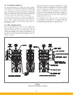
There are two primary modes of operation — the air filtering
operation and filter cleaning cycle. Both modes of operation are
shown in Figure 1.
!
DANGER
Summary of Contents for SFC
Page 1: ...Downward Flow Cartridge Dust Collector Owner s Manual Model SFC...
Page 7: ...v Page intentionally left blank...
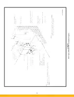
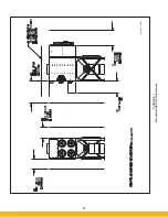
Page 11: ...4 FIGURE 2 SFC Typical SINGLE UNIT Installation Diagram PARKER PARKER 44 10335 0001...
Page 12: ...5 FIGURE 3 Recommended Unit Clearances 44 10337 0001...
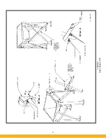
Page 14: ...7 FIGURE 4 Single Hopper SFC 44 10309 0001...
Page 15: ...8 FIGURE 5 Multiple Hopper SFC 44 10309 0002...
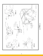
Page 16: ...9 FIGURE 6 Multiple Hopper SFC 44 10309 0003...
Page 17: ...10 FIGURE 7 Multiple Modules SFC 44 10310 0001...
Page 19: ...12 FIGURE 8 SFC Pressure Gauge Installation 44 10333 0001 Rev A...
Page 20: ...13 FIGURE 9 Solenoid Wiring to Pulse Controls for 2 3 4 and 5 Tier Units...
Page 21: ...14 FIGURE 10 Pneumatic Valve Assembly 44 10332 0001...
Page 24: ...17 FIGURE 12 Abrasive Inlet Installation 44 10338 0001...
Page 27: ...20 FIGURE 16 EDAP Interconnection FIGURE 15 EDAP Installation 48 10007...
Page 30: ...23 FIGURE 17 SFC Series Door Filter Installation 44 10329 0001...
Page 37: ...30 7 Illustrated Parts FIGURE 21 SFC Series 44 10330 0001 FIGURE 22 SFC Series Explosion Vents...


