


11
Disconnect lifting slings and spreader bars used for installation.
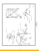
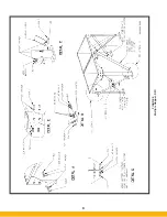
Apply sealant to the next hoppers that will receive a filter module
(refer to Figure 7). Apply sealant to the side bolting flange of
the next filter module to be installed using the “figure 8” pattern
(refer to Figure 7, Detail B). Place this module on its hopper. Use
the hardware provided (refer to Figure 7, Detail B).
Place this module on its hopper. Use the hardware provided
(refer to Figure 7, Detail B) and bolt the module sections
together. Bolt the filter module to the hopper (refer to Figure 7,
Detail A). Securely tighten all hardware at the filter module and
hopper. Recheck leg assembly sway braces to ensure they are
tight. Install fasteners (bolt, flat washer, lock-washer, nut) to all
four pry locations.
Disconnect lifting slings and spreader bars used for installation.
Repeat this process until all the module sections are in place,
securely fastened and anchored to the foundation. Recheck all
hardware connections to make certain they are securely tight-
ened. Remove lift slings and spreader bars and clear all tools
from the work area.
NOTE: Make certain all bolts (including the anchor bolts) are
properly tightened before proceeding with the remain-
der of the installation.
Install all cartridge filters removed at the beginning of the instal-
lation process and install the filter access doors (refer to Section
5.1).
3.4 Electrical Installation
ELECTRICAL SHOCK HAZARD
All electrical work should be performed by a qual-
ified electrician in accordance with local electrical
codes. Disconnect electrical power before install-
ing or servicing any electrical component.
General
Several types of standard electrical components can be
installed to control and monitor your dust collector. A VFD or
a motor starter circuit (combination starter panel) is required to
safely start and stop the system. A properly sized circuit breaker
or fused disconnect is also required to safely work on and
service the electrical system. In addition, a 115/1/60 (2 amp)
control circuit is required for the pulse control panel. Some or
all of the above items may be included in the controls package
you purchased from Parker. Any one of the following control
combinations can be used:
• Motor starter with Digital Pulse Monitor (DPM) for continuous
pulse cleaning.
• Motor starter with Digital Pulse Control (DPC) for on-demand
pulse cleaning.
• VFD with DPM for continuous pulse cleaning.
• VFD with DPC for on-demand pulse cleaning.
Refer to Parker sales order to verify the control configuration
purchased with your unit and whether additional items are
required to control and operate your system.
3.4.1 Mounting The Controls
Mount the VFD or combination starter panel for the fan motor
in a convenient location. It is recommended that these controls
be mounted on a wall or pedestal in an area subject to minimal
vibration and electrical noise. Mounting hardware is provided by
the customer or the contractor. If the panel includes the DPM or
the DPC gauge and Parker timer control board, then the location
of the panel must within close proximity of the dust collection
unit as shown in Figure 8. For additional setup and installation
information refer to the VFD and/or DPM/DPC Owner’s Manuals
provided.
Avoid mounting the panel on the collector due to
vibration generated from blower assembly and the
pulsing system.
For all pulse control panels, connect the black plastic pressure
tubing (25’ [7.5 meters] provided by Parker) to the panel fittings
and the SFC unit. Connect the dirty air plenum of the SFC to
the high pressure port (dirty air) on the panel as shown in Figure
8. Connect the clean air plenum of the SFC to the low pressure
port (clean air) on the panel.
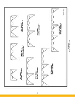
3.4.2 Solenoid Valve Enclosure Wiring
The solenoid valves at the dust collector must be wired cor-
rectly to the pulse control panel. Refer to Figure 9 when making
connections from the pulse control panel to the solenoid valve
enclosure(s).
Example: Figure 9 shows the SFC having ten valve locations
per module. This means when the system pulses, “1” is the first
pulse in the sequence, “2” is the second, “3” is the third, etc.
When multiple dust collector modules are installed,
daisy chain the wiring so that each solenoid valve with the
same module location will pulse at the same time. This means
all #1 solenoid valves are connected together and wired to
pulse control panel “OUT 1,” #2 solenoid valves are connected
together and wired to pulse control panel “OUT 2,” etc. Refer
to Figure 9 for the SFC dust collector solenoid valve wiring
information. When cleaning, the pulse valves sequence left to
right, top to bottom.
Unless specified on the Parkerr sales order, the customer will
supply interconnecting material (conduit, wiring, etc.) from the
pulse control panel to the SFC
.
CAUTION
!
D A N G E R
Summary of Contents for SFC
Page 1: ...Downward Flow Cartridge Dust Collector Owner s Manual Model SFC...
Page 7: ...v Page intentionally left blank...
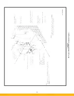
Page 11: ...4 FIGURE 2 SFC Typical SINGLE UNIT Installation Diagram PARKER PARKER 44 10335 0001...
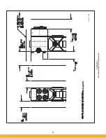
Page 12: ...5 FIGURE 3 Recommended Unit Clearances 44 10337 0001...
Page 14: ...7 FIGURE 4 Single Hopper SFC 44 10309 0001...
Page 15: ...8 FIGURE 5 Multiple Hopper SFC 44 10309 0002...
Page 16: ...9 FIGURE 6 Multiple Hopper SFC 44 10309 0003...
Page 17: ...10 FIGURE 7 Multiple Modules SFC 44 10310 0001...
Page 19: ...12 FIGURE 8 SFC Pressure Gauge Installation 44 10333 0001 Rev A...
Page 20: ...13 FIGURE 9 Solenoid Wiring to Pulse Controls for 2 3 4 and 5 Tier Units...
Page 21: ...14 FIGURE 10 Pneumatic Valve Assembly 44 10332 0001...
Page 24: ...17 FIGURE 12 Abrasive Inlet Installation 44 10338 0001...
Page 27: ...20 FIGURE 16 EDAP Interconnection FIGURE 15 EDAP Installation 48 10007...
Page 30: ...23 FIGURE 17 SFC Series Door Filter Installation 44 10329 0001...
Page 37: ...30 7 Illustrated Parts FIGURE 21 SFC Series 44 10330 0001 FIGURE 22 SFC Series Explosion Vents...