


Drive Controlled Pump
Parker Hannifin Corporation
Hydraulics Group
DCP Manual innen A4 UK.indd 06.11.17
67
Manual
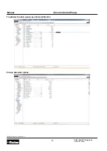
Configure the drive
Quick Setup
In the menu “Setup“
→
“Quick Setup“a basic config-
uration can be operated.
Step 1:
Select Application
Q_Control
P_Control
LS_Control
Accumulator_Control
pQ_Control
Step 2:
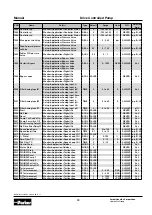
DCP Pump code
Enter DCP Pump type (see order code)
DCP3xxxxxxxxxxxL2414
After setting the correct pump code, all rele-
vant parameters of the pump will be set au-
tomatically. (double pump, displacement, min.
speed of the pump, max. speed of the pump,
max. pressure of the pump)
Fixed Parameter:
Double pump
Displacement of the pump
Max. pressure of the pump
Adjustable parameters:
Min. pump speed (adjustment pump speed
min
→
pump speed max)
Max. pump speed (adjustment pump speed
max
→
pump speed min)
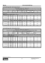
If the pump code
DCP3xxxxxxxxxxx0000
is used, all pa-
rameters of the pump can be set individually.
The automatic protection of the pump, that is ensured
when inserting the DCP-code, is not given anymore.The
speed and pressure range of the motor/pump have to be
set manually.
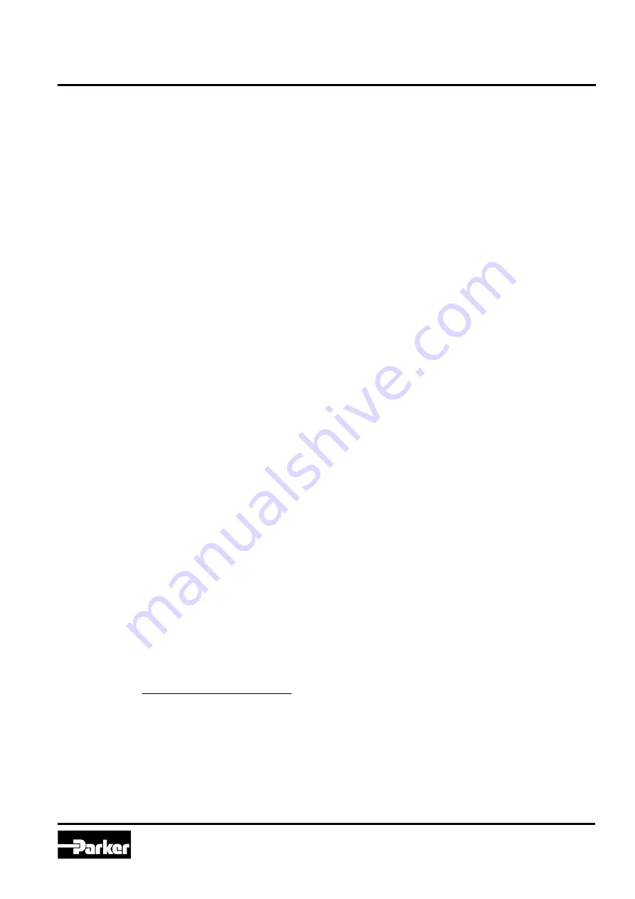
Step 3
→
9 = Example of a pQ-Application
Step 3:
Qmax at 100% AIN02:
Qmax at 100% input at analogue input 02.
Qmax= Displacement ccm*100 % Speed rpm
1000
If the target-flow is sent via fieldbus, this pa-
rameter is not required.
Step 4:
Pmax at 100% AIN02/11:
Maximum target pressure at 100% input at an-
alog input 02 (Application p/LS- Control) or an-
alog input 11 (Application pQ-Control).
If the target-pressure is sent via fieldbus, this
parameter is not required.
Step 5:
Upper Limit pressure:
Limits the maximum pressure of the drive. If
the max. pressure > max. pressure pump 1/2,
then max. pressure = max. pressure pump 1/2.
Step 6:
Max. p for sensor p0: [bar]
This parameter sets the maximum pressure of
the pressure transducer at 100% input signal.
Step 7:
Pressure ramp up: [Bar/s]
Pressure ramp down: [Bar/s]
Step 8:
Max. p pressure valve: [bar]
This parameter sets the max. pressure of the
pressure valve at 100% input on the PCD-mod-
ule.
It is only used, if a pressure valve is connect-
ed to analog output 02.
Step 9:
Feed Forward p-Valve:
This parameter sets the value of the feed for-
ward and accordingly the control reserve of the
pressure valve. If the pressure valve opens be-
fore the drive reaches the min. speed, the val-
ue has to be increased. (default value: 10%)
Detailed settings can be set in the menu: Set-
tings
→
Application.
Bypass Valve (Hysterisis Bypass)
“Flow-time and -window” for “Flow Reached”.
“Pressure-time and -window” for “Pressure
Reached”.
Filter analog inputs.