


Drive Controlled Pump
Parker Hannifin Corporation
Hydraulics Group
DCP Manual innen A4 UK.indd 06.11.17
21
Manual
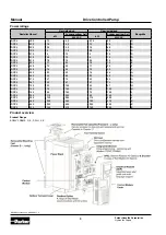
Terminal
Name
Range
Description
X21/01
AN 0V
0 V
Analogue signal
reference
X21/02
ANIN11
-10 V to 10 V
Analogue Input 11
X21/03
ANIN12
-10 V to 10 V
Analogue Input 12
X21/04
ANIN13
-10 V to 10 V
Analogue Input 13
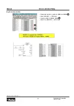
Analogue Inputs
Note:
These analogue input ports are differential. That means
that the signal reference on terminal X20/01 is not direct-
ly connected internally to the drive 0 V terminal.
Therefore X21/01 must be connected to the user 0 V sig-
nal reference with should be grounded at an appropriate
point in the system.
If any analogue input are unused, they should be con-
nected to X21/01 to prevent invalid values being reported.
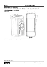
Example:
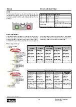
Motor Thermistor
Motor Thermistor
Terminal
Name
Range
Description
X22/01
TH1
0 to
4.5 k
Ω
Connect motor thermistor
between these two
terminals.
X22/02
TH2
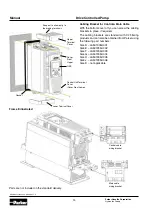
Terminal
Name
Range
Description
X22/01
TH1
0 to
4.5 k
Ω
Connect motor thermistor
between these two
terminals.
X22/02
TH2
Example:
Example:
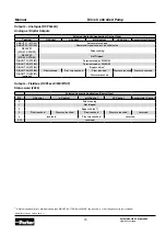
Volt-free Relays
Terminal
Name
Range
Descripiton
X23/01
RLY11A
3A @ 250 V AC
3A @ 30 V DC
Terminal A of Relay 11
X23/02
RLY11B
Terminal B of Relay 11
X23/03
RLY12A
Terminal A of Relay 12
X23/04
RLY12B
Terminal B of Relay 12
Encoder and Motor Thermistor