


Drive Controlled Pump
Parker Hannifin Corporation
Hydraulics Group
DCP Manual innen A4 UK.indd 06.11.17
29
Manual
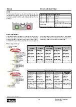
1)
Do not connect both X10/02 and X10/4 to earth, otherwise an earth loop could be created.
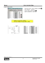
User connections
The STO terminals are on a 6-way terminal block X10. This is mounted on the AC30V control housing. Terminal des-
ignations are:
Truth table
Terminal Number
Terminal Name
Description
X10/01
STO A Input
0V or not connected = drive will not run, STO is active on channel A. 24V = drive is enabled
to run if X10/03 is also 24V. This input is optically isolated from all other AC30V terminals ex-
cept X10/02, X10/03 and X10/04.
X10/02
STO Common 3
Signal return for STO A Input and STO B Input. Connected internally to X10/04. This termi-
nal or X10/04 must be connected to earth at one common point in the drive system.
X10/03
STO B Input
0V or not connected = drive will not run, STO is active on channel B. 24V = drive is enabled
to run if X10/01 is also 24V. This input is optically isolated from all other AC30V terminals ex-
cept X10/01, X10/02 and X10/04.
X10/04
STO Common 2
Signal return for STO A Input and STO B Input. Connected internally to X10/02. This termi-
nal or X10/02 must be connected to earth at one common point in the drive system.
X10/05
STO Status A
Together with X10/06, this terminal forms an isolated solid-state relay output. This output
is ON (equivalent to closed relay contacts) when the STO circuit is in the ‘safe’ state, i.e. the
drive will not cause its motor to produce torque. However, this output should be used pri-
marily as an indication. In the unlikely event of a fault in the STO circuit, this output could
turn on erroneously to give a false indication of the STO status. It must not be used as a gu-
arantee that the motor will not produce torque. The solid-state relay is protected by a self-
resetting fuse.
X10/06
STO Status B
Together with X10/05, this terminal forms an isolated solid-state relay output. See the de-
scription for X10/05.
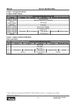
Overview
STO Input
A
X10/01
STO Input
B
X10/03
Drive Function
STO Status Output
X10/05, X10/06
STO Active
0V
0V
Drive cannot start or supply power to its motor. STO trip re-
ported. This is the intended safe state of the product with
correct dual-channel operation.
ON
Abnormal one-
channel operation
detection
24V
0V
Drive cannot start or supply power to its motor. STO trip re-
ported. If either of these conditions persists for more than
3.0 seconds (the maximum fault detection time), the STO
function will lock into a fault state. The drive cannot start un-
til the fault is rectified; all power is removed and reapplied
(both mains and any auxiliary 24V dc power). This is single
channel operation and thus deemed not as intended for ca-
tegory 3 / PLe / SIL3 structure implementation.
OFF
0V
24V
STO Inactive
24V
24V
Drive is enabled to run under software control. The drive can
supply power to its motor.
OFF
Drive unpowered
Don’t care
Don’t care
Drive cannot start or supply power to its motor.
OFF