


Drive Controlled Pump
Parker Hannifin Corporation
Hydraulics Group
DCP Manual innen A4 UK.indd 06.11.17
30
Manual
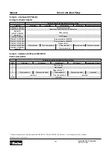
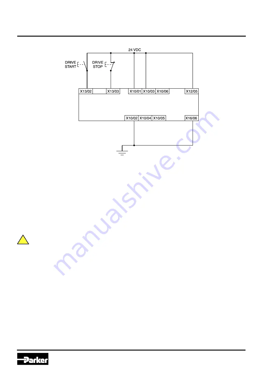
Applications that do not require STO function
STO inputs X10/01 and X10/03 must be connected to
24VDC with respect to terminals X10/02 or X10/04.
STO Status output on X10/05 and X10/06 may be left
disconnected.
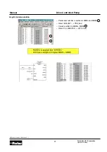
All wiring shown is within the control cubicle.
Here the STO inputs X10/01 and X10/03 have been set
to the inactive state (tied to +24V). Drive control is per-
formed solely through software with no inherent safe-
ty function. The drive is controlled with its own start and
stop pushbuttons.
Only X10/02 or X10/4 must be earthed, i.e. they
should not both be earthed otherwise it is possible
to create an earth loop.
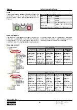
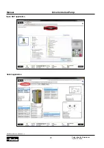
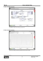
Applications
Description
The Drive Controlled Pump Applications provides 5 pump
control configurations:
• “Q” Control
• “P” Control
• “p/Q” Control (flow control with pressure control)
• “LS” control (Load sensing)
• Accumulator Control
Features
• Graphical user interface for hydraulic-functions
• Supports variable and fixed displacement pumps
• Drive parameter settings for Parker-pumps(v, n
max
,
a
max
, …) by order code
• Integrated control of optional bypass valve (on/off) and
proportional pressure relief valve
• Double pump: on/off control for low and high pressure
• Leakage compensation of Parker DCP Pumps
• Electrical power control
• Master-Slave pump control
Requirements
To use the AC30V for hydraulic control as described in
this manual, the application DCP_Application_Program
must be loaded into an AC30V series drive with firmware
1.10 or newer.