


Installation
2-5
3166-A2-GB20-20
March 1999
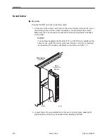
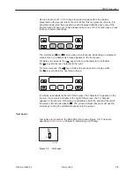
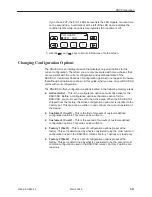
9. Attach the network cable to the NET connector on the rear connector module.
Connect the other end of the network cable to the connection provided by the
telephone company.
NET
DIA
GNOSTIC
CHANNEL
Network
98-16077
10. To daisy-chain the diagnostic channel with that of other 3166 DSU/CSUs or a
T1 auxiliary backplane, insert one end of the short diagnostic channel
extension cable into either DIAGNOSTIC CHANNEL connector on the rear
connector module. Insert the other end into either DIAGNOSTIC CHANNEL
connector of a neighboring 3166 rear connector module, or the diagnostic
channel connector of a T1 auxiliary backplane.
98-16080
PORT
1
PORT
1
PORT
1
PORT
1
PORT
1
PORT
1
PORT
1
PORT
1
CLOCK IN
DIAGNOSTIC
CHAN
PORT
2
PORT
2
PORT
2
PORT
2
PORT
2
PORT
2
PORT
2
PORT
2
DTE
DTE
DTE
DTE
DTE
DTE
DTE
DTE
SLT 8 (16)
SLOT 6 (14)
SLOT 7 (15)
SLOT 5 (13)
SLOT 4 (12)
SLOT 3 (11)
SLOT 2 (10)
SLOT 1 (9)
T1 NETWORK
INTERFACE
COMCODE
107170409
MODEL NO.
3100-F1-900
DIAGNOSTIC
CHAN
CAUTION:
DISCONNECT ALL TELEPHONE LINES AT THE NETWORK
INTERFACE BEFORE TOUCHING OR SERVICING
Diagnostic Channel
Extension Cable
NET
PORT 1
COM
DIAGNOSTIC
CHANNEL
NET
PORT 1
COM
DIAGNOSTIC
CHANNEL
Summary of Contents for 3166 DSU
Page 1: ...ACCULINK 3166 DSU CSU USER S GUIDE Document No 3166 A2 GB20 20 March 1999...
Page 16: ...About This Guide x 3166 A2 GB20 20 March 1999 This page intentionally left blank...
Page 20: ...Introduction 1 4 3166 A2 GB20 20 March 1999 This page intentionally left blank...
Page 68: ...SDCP Operation 3 42 3166 A2 GB20 20 March 1999 This page intentionally left blank...
Page 102: ...SDCP Menu A 2 3166 A2 GB20 20 March 1999 This page intentionally left blank...
Page 140: ...Pin Assignments D 12 3166 A2 GB20 20 March 1999 This page intentionally left blank...
Page 166: ...SNMP MIB Objects E 26 3166 A2 GB20 20 March 1999 This page intentionally left blank...
Page 192: ...Equipment List I 2 3166 A2 GB20 20 March 1999 This page intentionally left blank...