SMARTZONE G6 IRUPS USER MANUAL
17
12. Insert the connectors back into the middle hole on the chassis.
13. Reinstall the faceplate on the EBP, by aligning the front panel latches with the holes
in the front of the unit and snapping the faceplate onto the front of the EBP. Should
have a positive snap of the latches on the faceplate.
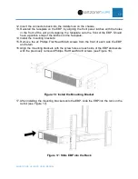
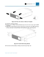
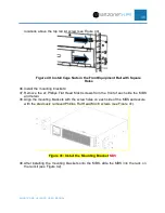
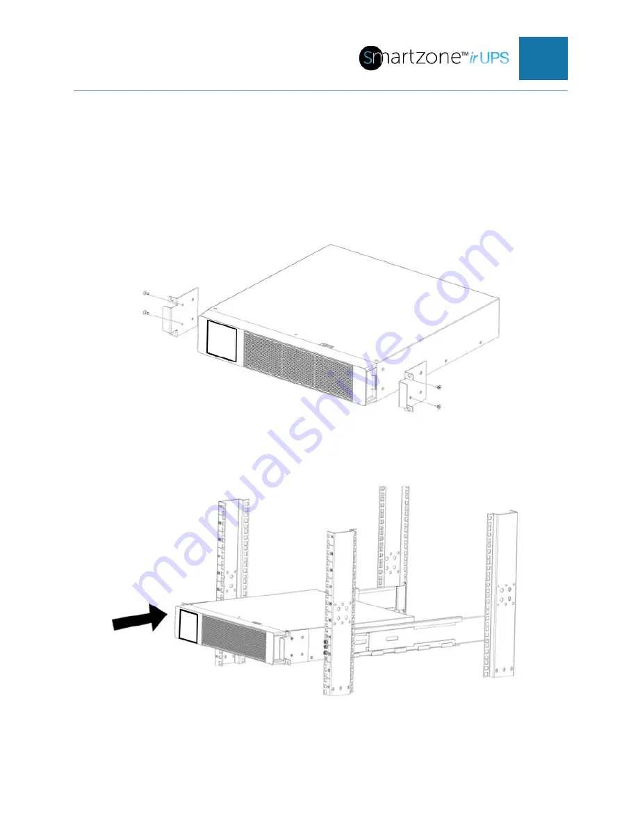
14. Install the mounting brackets:
15. Remove the 2x Phillips Flat Head M4x8 screws from the front of each side the EBP
and retain.
16. Align the mounting brackets with the screw holes on each side of the EBP and secure
with the previously removed Phillips Flat Head M4×8 screws (see Figure 16).
Figure 16: Install the Mounting Bracket
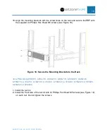
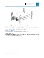
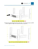
17. After installing the mounting brackets onto the EBP, slide the EBP into the rack on the
rail kit (see Figure 17).
Figure 17: Slide EBP into the Rack
Summary of Contents for Smartzone U01N11V
Page 66: ...SMARTZONE G6 IRUPS USER MANUAL 65 Appendix F What s Included 5 10kVA EBP UVP240 ...
Page 67: ...SMARTZONE G6 IRUPS USER MANUAL 66 Appendix G What s Included 10 20kVA EBP UVP480 ...
Page 68: ...SMARTZONE G6 IRUPS USER MANUAL 67 Appendix H What s Included Maintenance Bypass Switch UMB20K ...


