background image

13

Configure the Network Settings

With the following network environment, it is not necessary to configure the network settings. It is possible to config-
ure the settings or operate the recorder using the monitoring software after completing the connection.
IP Address: 192.168.0.2 - 192.168.0.249, 192.168.0.251 - 192.168.0.254
Subnet Mask: 255.255.255.0
Gateway Address: 192.168.0.1
When the network settings are different from the settings above, configure the network settings of the recorder and
the PC.

Configure the network settings of the recorder

Use the buttons on the front panel of the recorder to conform the network settings to the network environment of the
PC.
Refer to the installation guide of the recorder for further information about the network settings (The "Configure the
network settings [Network Setup]" section under the "Configure the settings relating to communication with other
devices [Communication Setup]" chapter in the descriptions of "Setup Menu").

Configure the network settings of a PC

Change the TCP/IP setting of the PC to conform to the settings of the recorder.
It is required to set the IP address of the PC to "192.168.0.XX (a number from 2 to 254 except 250)" to access the
recorder.

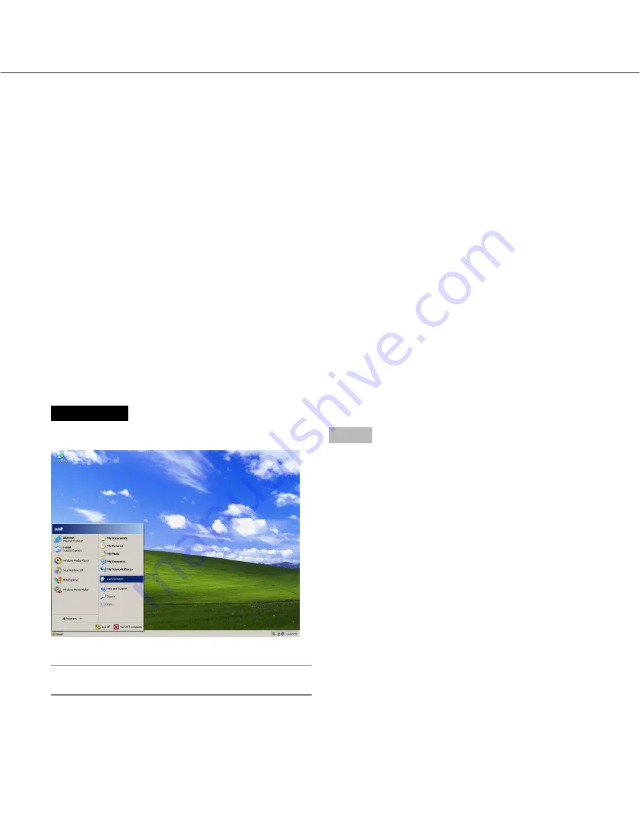
Screenshot 1

Start just after the PC is started up.

Important:

Log in to the PC as an administrator.

Step 1

On the taskbar, click "Start", and then click the "Control
Panel".

Summary of Contents for WJ-RT416/G

Page 1: ...LTI SCREEN TIMER ALARM RESET OPERATE REV FWD SKIP Digital Disk Recorder WJ RT416 Before attempting to connect or operate this product please read these instructions carefully and save this manual for future use The model number is abbreviated in some descriptions in this manual WJ RT416 is shown above This manual covers the models WJ RT416K WJ RT416V WJ RT416VK WJ RT416 G WJ RT416K G WJ RT416V G a...

Page 2: ...ntrol 41 Determination whether to enable or disable the alarm output from the AUDIO IN ALARM OUT terminal on the rear of the recorder Alarm Output Control 42 Reboot of the recorder Maintenance Reboot 42 Download upload of the setup data from to the recorder Setup Data Download Upload Maintenance Setup Data Download Upload 43 Download upload of the language data from to the recorder Language Data D...

Page 3: ...HE CORRESPONDING PRODUCT S IN NO EVENT SHALL Panasonic Corporation BE LIABLE TO ANY PARTY OR ANY PERSON EXCEPT FOR CER TAIN WARRANTY PROGRAM OFFERED BY THE LOCAL DEALER OF PANASONIC FOR THE CASES INCLUD ING BUT NOT LIMITED TO BELOW 1 ANY DAMAGE AND LOSS INCLUDING WITHOUT LIMITATION DIRECT OR INDIRECT SPECIAL CONSE QUENTIAL OR EXEMPLARY ARISING OUT OF OR RELATING TO THE PRODUCT 2 PERSONAL INJURY OR...

Page 4: ...wing RT4Client The principal functions of the monitoring software can be operated using the RT4Client To use the monitoring soft ware start the RT4Client first The following are the functions of the RT4Client Displaying of live images from the cameras normal display frame display sequential display Control of the cameras setup operation Playback of recorded images on the recorder Configuration of ...

Page 5: ...ging or the software becomes inoperable OS Microsoft Windows XP Professional SP2 Microsoft Windows XP Home Edition SP2 Tested and confirmed full compatibility with the English edition Full compatibility with other language editions cannot be guaranteed Computer IBM PC AT Compatible CPU Pentium 4 3 0 GHz or faster Memory 512 MB or more Graphic memory 256 MB or more Display driver Overlay compatible...

Page 6: ...following abbreviations are used in these operating instructions Microsoft Windows XP Professional SP2 and Microsoft Windows XP Home Edition SP2 are described as Windows XP MPEG 4 Visual patent portfolio license This product is licensed under the MPEG 4 Visual patent portfolio license for the personal and non commercial use of a consumer for i encoding video in compliance with the MPEG 4 Visual St...

Page 7: ...tant When using Windows XP Professional or Home Edition SP2 the Windows Security Alert window may be pos sible to be displayed In this case click the Unblock button on the displayed Windows Security Alert window When clicked the Block button accidentally do the following 1 Click Security Center on the Control Panel 2 Click the Exceptions tab 3 Check if the checkbox of the monitoring software is ch...

Page 8: ...illustration below The selected area will be displayed with a yellow frame Area selection buttons The clicked area will be displayed on a 1 screen page 17 Multi screen selection buttons Click the desired multi screen selection button The selected multi screen will be displayed in the image dis play area Status display area The status icons will be displayed to indicate the status es of each area R...

Page 9: ...tween the user levels Refer to page 19 for how to log in the recorder The following are available using the recorder control buttons Login logout page 19 Configurations of the recorder page 35 Download of recorded images page 47 Remote talk start end page 48 System control buttons Starting of each function of the monitoring software displaying of the setup menu etc can be made using these but tons...

Page 10: ...hen the information title is clicked the respective information will be displayed Recorder name Name of the current login recorder will be displayed Camera State The status of the camera connected to the current login recorder will be displayed Camera camera name State camera status Blank No signal Live The recorder is not in the process of recording or not connected to a network Manual The record...

Page 11: ...isplay style is the same as the display style of the error log of the recorder User Info User information of users who is currently accessing the recorder will be displayed IP Address Type Monitor User is monitoring live images Control User is being logged in the recorder using the monitoring software Backup User is downloading recorded images from the recorder Talk User is transmitting receiving ...

Page 12: ...password of the user level Viewer or Operator By setting the password of the user level Viewer it is possible to restrict users to operate the cameras Users whose user level is Manager can configure the settings of the cameras The default password is different according to the user level as follows Manager1 12345678 Operator1 123456 Viewer1 1234 To enhance the security change the password before r...

Page 13: ... the recorder to conform the network settings to the network environment of the PC Refer to the installation guide of the recorder for further information about the network settings The Configure the network settings Network Setup section under the Configure the settings relating to communication with other devices Communication Setup chapter in the descriptions of Setup Menu Configure the network...

Page 14: ... Click the Network and Internet Connections icon Screenshot 3 The Network and Internet Connections window will be displayed Step 3 Click Network Connections Screenshot 4 The Network Connections window will be displayed Step 4 Double click Local Area Connection ...

Page 15: ...will be displayed Step 6 Click Internet Protocol TCP IP and then click Properties Screenshot 7 The Properties window of Internet Protocol TCP IP will be displayed Step 7 Click Use the following IP address and enter the IP address and the subnet mask as follows IP Address 192 168 0 9 Subnet Mask 255 255 255 0 Step 8 Click the OK button and close the window ...

Page 16: ... camera channels of the same recorder or when displaying recorded images in an area on a multi screen only I frame will be displayed in all areas on a multi screen and audio may not be heard It is possible to display live images on a 1 screen or a multi screen in the image display area To monitor live images from the cameras select the desired camera connected to the recorder first Screenshot 1 St...

Page 17: ...ection button The selected multi screen will be displayed in the image display area 4 screen Each time this button is clicked the displayed area will change as follows 1 4 5 8 9 12 13 16 1 4 6 screen Each time this button is clicked the displayed area will change as follows 1 6 7 12 1 6 7 12 9 screen Areas 1 9 will be displayed in the image display area 16 screen Areas 1 16 will be displayed in th...

Page 18: ...efer to pages 49 and 50 for further information about the alarm recording Temporarily change color of text displayed in the image display area When right clicking on the text displayed on the image display area the pop up menu will be displayed Select White Magenta or Bright Green to change the color of the text temporarily Control the cameras The camera from which images are being displayed in th...

Page 19: ...ndow will be displayed Important Depending of the firewall setting of Windows XP SP2 recorder information may sometimes not be displayed Refer to page 7 for further information Step 1 Select the desired recorder and enter the password of the user level Manager Note Only the recorders registered in advance can be selected on the Login window Refer to page 12 for further information Step 2 Click the...

Page 20: ...o log in the recorder Important It is impossible to play recorded image which is currently being played or copied on the recorder Note When displaying images from 5 or more camera channels of the same recorder or when displaying recorded images in an area on a multi screen only I frame will be displayed on a multi screen audio may not be heard when displaying live images Play recorded images from ...

Page 21: ...ecorded by the alarm recording triggered by VMD Com Searches for only images recorded by the alarm recording triggered by a command alarm reception Start End Designate the time period to be searched by entering the start and end time and date Step 4 When the search filters are set click the OK button Screenshot 4 The search result window will be displayed Step 5 Select the desired recorded images ...

Page 22: ... completing the settings click the OK button Play recorded images from the search result window displayed after searching by designating the start time of recording Time Date Search Playback Screenshot 1 Start operation when the operation window is being dis played Step 1 Right click on a blank area in the image display area Screenshot 2 The pop up menu will be displayed Step 2 Select T D Search P...

Page 23: ...ext record When there is no recorded image at all playback will not start Operations during playback can be made using the con trol panel Refer to page 29 for further information Stop playback When playback is stopped the connection with the recorder will also be disconnected Screenshot 1 Start operation when the operation window is being dis played Step 1 Right click on the area where recorded im...

Page 24: ...24 Screenshot 2 The pop up menu will be displayed Step 2 Select Stop Playback Playback will stop and the connection with the recorder will be disconnected ...

Page 25: ...ct Control Panel from the pop up menu Close the control panel Click the button at the right top of the control panel or click on somewhere out of the selected area The control panel will be closed Save the image currently being displayed on the PC Click the Real Time Save button The image currently displayed will be saved The Real Time Save button will change as follows to indicate the current sta...

Page 26: ...ected in the Choose Directory section on the Advanced Setup window The Advanced Setup window can be displayed by selecting Advanced Setup under Monitor System Config from the pop up menu displayed when the Monitor System Setup button is clicked Note It is impossible to capture the recorded image when playback is being stopped Muting audio When the Mute button is clicked audio will be muted The Mut...

Page 27: ...n the right side of the control panel to control the camera Panning tilting Moves the camera horizontally AB vertically CD Zooming Zooms in out of images TELE WIDE Focusing Adjusts the focus FAR NEAR AF Adjusts the focus automatically Preset position Moves the camera to the preset position registered in advance Notes When Home is selected for Preset position the camera will move to the home positi...

Page 28: ...ed on the right side of the control panel Operation of the setup menu of the camera is available with these buttons To close the displayed extension panel and the setup menu of the camera click the B button again SET Determines the setting moves to the submenu ESC Moves to the parent page CDAB Moves the cursor changes the parameter Reset Displays the special menu Refer to the operating instruction...

Page 29: ...ausing and resume the playback Play frame by frame playback button Click this button to start playback When this button is clicked during paus ing the next frame will be displayed Fast forward playback button Fast forward playback speed will change in the following order each time the fast playback button is clicked 1x 2x 4x 1 4x 1 2x 1x 2x Next record button It is possible to select the next reco...

Page 30: ... Common Setup tab of the Recording Event Setup window page 36 The default of I Frame Interval is 4 The frame display switches the displayed image at 4 seconds interval Important When the value set for I Frame Interval is changed it also affects recording Screenshot 1 Click the Frame display button The Frame Display window will be displayed Step 1 Select the desired recorder and the cameras and the...

Page 31: ...screen display Step 3 To exit from the frame display click the button at the right top of the window Notes When 5 cameras are selected the frame display will start on a 9 screen as shown is the image of Screenshot 2 When the resolution setting Field SIF for the selected cameras are set differently frame display works only for the cameras whose resolution setting is the same as one for the youngest...

Page 32: ...K button to disconnect all the connec tion to continue operation Screenshot 2 The password entry window will be displayed Step 2 The password registered when registered the recorder will be entered automatically Click the OK button The sequential display will start Step 3 To stop the sequential display click the Stop sequential display button When the sequential display starts the Sequential displ...

Page 33: ...click the OK but ton The password registered when registered the recorder will be entered automatically Images from the registered camera channel as favorite will be displayed in the assigned area Important When images are currently being displayed discon nect all the connections Click the OK button to disconnect all the connec tion to continue operation When the camera of which the camera channel...

Page 34: ...e camera that is not available for live image monitoring Not connected When clicking on the pop up menu will be dis played When selecting Connect from the pop up menu the connection window will be displayed Enter the password and then click the OK button Connection with the selected camera will be estab lished and live image monitoring will become avail able When clicking on and selecting Disconne...

Page 35: ...the pop up menu will be displayed Note Available operations differ depending on the login user Configuration of the settings of the recorder System Setup Setup System Setup Configure the basic settings relating the system of the recorder Screenshot 1 Select System Setup under Setup from the pop up menu The System Setup window will be displayed Step 1 The setup items on the System Setup window are ...

Page 36: ...completing the settings click the Apply button Note The setting of compensation cable loss will be ignored when receiving any alarm from cameras during communication setup When the compensation is not set to S stop recording before changing the settings Screenshot 1 Select Recording Event Setup under Setup from the pop up menu The Recording Event Setup window will be dis played Step 1 The setup it...

Page 37: ...he NTP server Default Off NTP Server Address Enter the NTP server address when On is selected for NTP Synchronization Enter up to 128 alphanumeric characters including hyphens periods and underscores _ Refresh Interval Select an interval of time inquiry to the NTP server from the following 1h 2h 6h 12h 24h Default 1h ...

Page 38: ...ant Do not change the SMTP port number unless send ing mails using the submission port port number 587 POP Server Address When selecting POP before SMTP for Authentication enter the IP address of the POP serv er Entry of a POP server name is available only when selecting Manual or Auto for DNS Enter up to 128 alphanumeric characters including hyphens and periods Authentication Select an authentica...

Page 39: ...r Enter a port number to be used to transmit a Panasonic alarm protocol to the PC Default 1818 Destination Address Enter the address of the recipient Enter the IP address or host name for Address1 Address4 Enter up to 128 alphanumeric characters including hyphens periods and underscores _ Up to 4 destinations can be registered ...

Page 40: ... be kept When more than 100 event logs are filed the older event logs will be overwrit ten by the newer event logs In this case the oldest log is the first to be overwritten The descriptions of the network logs are as follows SMTPPOP3ATTEST_ERR POP3 authentication error SMTPPOP3SVR_ERR Failed to find POP3 server SMTPPOP3ADD_ERR Failed to resolve POP3 server address SMTPATTEST_ERR SMTP authenticati...

Page 41: ...stop the manual record ing On Starts the manual recording using this software Off Stops the manual recording using this software Step 2 Click the Apply button The selected operation will be carried out Check of the system information and disk information of the recorder Information It is possible to check the system information and the disk information of the recorder Select Information from the p...

Page 42: ...eckbox to stop outputting the alarm out put signal Step 2 To close from the Alarm Output Control window click the button at the right top of the window Reboot of the recorder Maintenance Reboot Select Reboot under Maintenance from the pop up menu page 35 The confirmation window will be displayed When the OK button on the confirmation window is clicked the reconfirm window will be displayed Click t...

Page 43: ...utton and then select the setup data to be uploaded Step 2 Click the Upload button Upload of the setup data will start Note The settings on the Network setup tab of the Communication Setup window will not be overwrit ten even when the setup data is uploaded Download upload of the setup data from to the recorder Setup Data Download Upload Maintenance Setup Data Download Upload Select Setup Data Dow...

Page 44: ...hen click the Save button Download of the language data will start Upload the language data Click the Choose File button and then select the language data to be uploaded Step 1 Click the Upload button Upload of the language data will start Notes Available characters for the custom language are as follows Some characters may not be displayed Basic Latin Latin Extended A Cyrillic Depending on the nu...

Page 45: ...ick the Save button after designating the destination folder Download of the mail template will start Upload the mail template Click the Alarm Mail tab or the Error Mail tab Click the Choose File button and select the template to be uploaded Then click the Upload button Upload of the mail template will start Notes Refer to page 81 for how to edit the contents of the mail It is recommended to downl...

Page 46: ...isplayed Step 2 Click the Firmware Update button Update of the firmware will start To validate the updated firmware reboot the recorder Important Before rebooting the recorder make sure that the recorder is not in the process of recording playback and copying Upload web data to the recorder To upload web data to be used when accessing the recorder using a web browser do the following Select Web Da...

Page 47: ...arches for only images recorded by the manual recording Timer Searches for only images recorded by the timer recording Alarm Searches for only images recorded by the alarm recording triggered by a terminal input VMD and a command alarm recep tion Terminal Searches for only images recorded by the alarm recording triggered by a terminal input VMD Searches for only images recorded by the alarm record...

Page 48: ...te button page 26 only audio of playback will be muted Screenshot 2 The result list will be displayed in the Data Download window Step 3 Click the Choose Directory button and then designate the directory in which recorded images are to be down loaded Step 4 Select the desired recorded images from the result list To select all of the listed recorded images click the Select All button Note It is pos...

Page 49: ...egistration of the recorder to be operated using this software Edit of the recorder information Edit of the camera information Screenshot 1 Select Recorder Setup under Monitor System Config from the pop up menu The Recorder Setup window will be displayed Step 1 Configure the settings on the Recorder Setup window Refer to the following for further information about the setup items on the Recorder S...

Page 50: ... the selected camera can be made Click the desired camera icon and then click the Edit button Edit Name up to 12 characters or Rec Duration To apply the edited item click the OK button Images recorded by the alarm recording will be stored the Mpeg folder in the directory selected in the Choose Directory section on the Advanced Setup window Important The same camera channel name cannot be applied t...

Page 51: ...ect the favorite name Favorite1 Favorite10 from the pull down menu Step 2 Select the recorder to access and the desired camera channels to be assigned to each area It is also possible to assign the desired camera channel by dragging the desired camera icon in the tree view onto the desired area icon Step 3 To cancel all of the assignments click the Clear but ton To edit the name of the favorite cl...

Page 52: ... the Normal Sequence tab and the My Favorite Sequence tab On the Normal Sequence tab the settings for the sequential display using the cameras connected to the registered recorder can be configured On the My Favorite Sequence tab the settings for the sequential display using the cameras registered as favorite can be configured Total time Dwell Time and Screen Mode are the common settings to be app...

Page 53: ...reen Mode Select a screen mode to be used for the sequential dis play from 1 4 9 and 16 The default is 4 4 screen Map Setup Monitoring System Config Map Setup Set a map diagram of the camera location arrangement used for the map display When remotely operating the recorder the map offers a visual way of understanding the camera locations Screenshot 1 Select Map Setup under Monitor System Config fr...

Page 54: ... etc The background image should be a bitmap image bmp or a jpeg image jpeg To cancel the applied background image click the Clear button Step 3 Click the Layout button Screenshot 3 The Map Edit window will be displayed Step 4 Locate each of the camera icons onto the actual posi tions on the background image Step 5 Click the OK button The Map Edit window will close Step 6 Click the Close button on...

Page 55: ...tle Setup Information to be displayed on the monitor can be selected Check the desired checkbox to display the respective information Time Date When displaying live images the current time and date will be displayed When displaying recorded images the recording time and date will be displayed Stream The speed of image transmission will be dis played Recorder Name The recorder name will be displaye...

Page 56: ...toring software will be displayed Language Select Language from the pop up menu page 49 The current display language has been selected during the process of the installation Select the display language from the following Chinese Custom English Japanese The default language of the custom language is English It is possible to customize the characters to be displayed by editing the Cst ini file in th...

Page 57: ...wnloaded recorded image page 59 Search File S Search for a file downloaded recorded image When Search File is selected the Search File window will be displayed page 60 Full Screen W Downloaded recorded images will be played on a full screen Exit X Exit the RT4Viewer Tool The following menu is under the Tool T menu Alteration Detection A Check whether the down loaded recorded image selected in the ...

Page 58: ...next frame will be displayed Pause button Playback will pause Stop button Playback will stop Previous record button Start playback of the previous record Next record button Start playback of the next record Playback speed slider Adjust the playback speed Original playback speed button Reset the adjusted playback speed to the original playback speed Save button Save the recorded image currently bei...

Page 59: ... and click the Play button Playback of the selected file will start in the image dis play area Control the playback image using the playback control buttons To display on a full screen select Full Screen under File on the menu bar or double click on the image currently being played To return to the previous size double click on the image currently being played again ...

Page 60: ...ed Screenshot 1 Select Search File S under File F on the menu bar The Search File window will be displayed Step 1 Set the desired search filter Select Channel Check the checkbox of the desired camera channel to be searched To select all the camera channels check the All checkbox Time Range Designate the time range to be searched by designating the recording start time and the end time Step 2 Click...

Page 61: ...en completing the alter ation check the message window will be displayed Step 3 Click the OK button Screenshot 2 The result of the alteration check will be displayed in the Alteration column of the playback list display area Step 4 Check the result Yes Altered No Not altered Undefined Notes When other file is opened the result will be cleared The result of alteration check will be Yes for files cr...

Page 62: ...ile Conversion under Tool The File Conversion window will be displayed Step 1 Click the File Conversion tab Step 2 Select the folder in which the file to be converted is located by clicking the Choose Directory button of File Path Then select the file to be converted from the displayed list Step 3 Designate the destination folder of the converted file by clicking the Choose Directory button of Sav...

Page 63: ...tings are different from the settings above configure the network settings of the recorder and the PC Configure the network settings of the recorder Use the buttons on the front panel of the recorder to conform the network settings to the network environment of the PC Refer to the installation guide of the recorder for further information about the network settings The Add the recorder to a broadb...

Page 64: ...Operable functions of the recorder vary depending on the user level Depending on the settings of the recorder it is possible to restrict users to monitor images from the cameras by setting the password of the user level Viewer or Operator By setting the password of the user level Viewer it is possible to restrict users to operate the cameras The default password is different according to the user ...

Page 65: ...ed Follow the instructions of the wizard When the install wizard is displayed again even after completing the installation of the ActiveX restart the PC To delete the installed ActiveX use RT4WebClear bat on the provided CD ROM When double clicking RT4WebClear bat the dialog box asking to confirm the deletion of the installed files will be displayed Press the y key on the keyboard and then press t...

Page 66: ...selection buttons The clicked area will be displayed on a 1 screen Multi screen selection buttons Images from up to 16 cameras can be displayed on a multi screen Click the desired multi screen selection button The selected multi screen will be displayed in the image dis play area Login Control Click to log in to the recorder It is necessary to log in to the recorder to play download recorded image...

Page 67: ...lay area To monitor live images from the cameras select the desired camera connected to the recorder first Screenshot 1 Start operation when the operation window is being dis played Step 1 Right click on a blank area in the image display area Screenshot 2 The pop up menu will be displayed Step 2 Select Connect ...

Page 68: ... more have been selected images from the second and the following cameras will be dis played in blank areas of the image display area in order Notes The current time and date of the recorder and the camera channel number will be displayed on live images When displaying images from 5 or more camera channels of the same recorder or when displaying recorded images in an area on a multi screen only I ...

Page 69: ... the image display area Temporarily change color of text displayed in the image display area When right clicking on the text displayed on the image display area the pop up menu will be displayed Select White Magenta or Bright Green to change the color of the text temporarily Control the cameras The camera from which live images are being displayed in the image display area can be controlled using ...

Page 70: ... action Moves a camera to the preset position registered in advance Note When 0 is entered for Preset the camera will move to the home position only when controlling Panasonic s camera Refer to the operating instructions of the camera for how to configure the related settings Disconnect the connection with camera Screenshot 1 Start operation when the operation window is being dis played Step 1 Rig...

Page 71: ...l be displayed Step 3 Select Disconnect The connection with the selected camera will be dis connected Note When Disconnect on All Areas is selected all cam eras from which the currently displayed images live playback will be disconnected ...

Page 72: ...Manager1 Manager4 Screenshot 1 Click the Manager Login button under Login Control The Login window will be displayed Step 1 Enter the manager password Step 2 Click the OK button When the connection is established the Manager Login button on the operation window will change to the Manager Logout button Click this button to log out of the recorder ...

Page 73: ...an transmit recorded images of 4 camera channels When the recorder is in the process of the playback image transmission only I frames of live images will be transmitted It is impossible to play recorded image which is currently being played or copied on the recorder Play recorded images from a result list displayed after searching with the designated search filters List Search Playback Screenshot ...

Page 74: ... the alarm recording triggered by VMD Com Searches for only images recorded by the alarm recording triggered by a command alarm reception Start End Designate the time period to be searched by entering the start and end time and date Step 4 When the search filters are set click the OK button Screenshot 4 The search result window will be displayed Step 5 Select the desired recorded images to be play...

Page 75: ... desired camera to be searched Start Enter the start time and date for the search Step 3 When completing the settings click the OK button Screenshot 3 Playback of images recorded in the designated time and date will start in the area selected in step 1 Step 4 Operations during playback can be made using the con trol panel Refer to page 76 for further information Notes When no recorded image was fo...

Page 76: ...utton Click this button to pause playback Click the Play button again to release pausing and resume the playback Frame by frame playback button When this button is clicked during pausing the next frame will be displayed Play button Click this button to start playback Fast forward playback button Click this button to start fast forward playback Fast forward playback speed will change in the followi...

Page 77: ...ng played Screenshot 2 The pop up menu will be displayed Step 2 Select Stop Playback Playback will stop and the connection with the recorder will be disconnected Notes When Disconnect on All Areas is selected all cam eras from which the currently displayed images live playback will be disconnected It is also possible to stop playback and disconnect the connection with the recorder clicking the Sto...

Page 78: ...designating the camera channels recording type and the start time and the end time of recording Screenshot 1 Start operation when the operation window is being dis played Step 1 Right click on the area where recorded images are being played Screenshot 2 The pop up menu will be displayed Step 2 Select Data Download ...

Page 79: ...s check the All checkbox Filtering Select the recording type Off Searches without filtering Manual Searches for only images recorded by the manual recording Timer Searches for only images recorded by the timer recording Alarm Searches for only images recorded by the alarm recording triggered by a terminal input VMD and a command alarm recep tion Terminal Searches for only images recorded by the al...

Page 80: ...ded images to be down loaded cannot be edited It is impossible to download recorded images which is currently being played or copied on the recorder or which is currently being played using the monitor ing software Language Select the display language from the following English Japanese Chinese Custom The default language of the custom language is English Contact your dealer for how to customize t...

Page 81: ...2000 Thermal Error Thermal error Fan x Error Fan error x indicates the fan number HDD Full No available disk space when overwrite is not permitted HDD x Access Error HDD error X indicates the HDD number HDD x SMART HDD S M A R T warning X indi cates the HDD number Cam xx Video Loss Video loss xx indicates the camera number Cam xx Get Signal Video signal recovered xx indi cates the camera number Pa...

Page 82: ...er to a system administrator if it is not lit Is the valid IP address set Refer to a system administrator for further informa tion 63 Are you accessing the wrong IP address Check the connection as follows ping IP address of this unit If there is reply from this unit the connection is nor mal If not check the settings of the IP address and the subnet mask Is the same IP address provided to other de...

Page 83: ...a tion Is the connection indicator of the 10BASE T 100BASE TX port lit When it is not lit connection to a LAN is not estab lished or a network is not working correctly Confirm that the connection indicator of the 10BASE T 100BASE TX port is lit Refer to a system adminis trator if it is not lit Are there contradictions between the address and the network subnet to be accessed When this unit and the...

Page 84: ... when playing on RT4Viewer It takes some time to start playback after the search Cannot perform frame by frame playback Close all applications except RT4Viwer The hard disk in which the images to be played are stored may be in the stand by mode It may take some time for the hard disk to resume from the stand by mode and start playback This is not malfunction The first operation of frame by frame p...

Page 85: ...mera The displayed images are not fit into the frame border Is the UDP port 999 of the router that is connected to the PC open Refer to the Connection with a PC section of the installation guide Images may not be displayed properly when 120 dpi is set for the dpi setting Right click on the desktop and select Properties from the displayed pop up menu Click the Advanced button on the Settings tab pa...

Page 86: ...cate Click the information bar and select Install ActiveX Control The Security Warning window will be displayed Click the Install button on the displayed Security Warning window Click the information bar and select Always Allow Pop ups from This Site The dialog window saying Allow pop ups from this site will be displayed Click the Yes button Solutions The following message is displayed on the info...

Page 87: ...on to open the Security Setting window Under Miscellaneous select Enable for Allow script initiated windows without size or position constraints Click the OK button The Warning window will be displayed Click the Yes button Solutions An unnecessary status bar or scroll bar is displayed on the pop up window Reference pages Symptom ...

Page 88: ...Secaucus New Jersey 07094 U S A Panasonic Canada Inc 5770 Ambler Drive Mississauga Ontario L4W 2T3 Canada 905 624 5010 www panasonic ca Panasonic System Networks Co Ltd 2010 N1106 7010 1 V8QB6495HN Printed in China For European and other fields http panasonic net Importer s name and address to follow EU rules Panasonic Testing Centre Panasonic Marketing Europe GmbH Winsbergring 15 22525 Hamburg F ...

Reviews: