background image

20

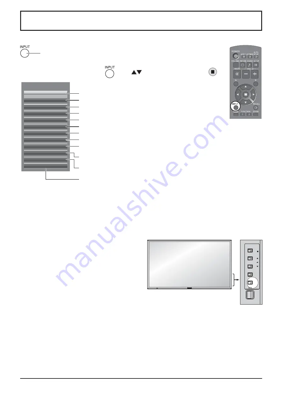
Selecting the input signal

Press to select the input signal to be played back from the equipment which has been 
connected to the Display.

Alternatively you can press 

, press 

 to select the input and press 

.

INPUT

HDMI1

HDMI2

SLOT INPUT

VIDEO

COMPONENT

PC

DVI

DIGITAL LINK

Miracast(TM)

Panasonic APPLICATION

WHITEBOARD

MEMORY VIEWER

HDMI input in HDMI 1 terminal

HDMI input in HDMI 2 terminal

Input signal in a Terminal Board*

1

Composite video input in VIDEO terminal

Component/RGB input in COMPONENT/RGB IN terminal*

2

Computer's signal input in PC IN terminal

DVI-D input in DVI-D IN terminal

DIGITAL LINK input in DIGITAL LINK terminal

Select this input when using the Miracast function. (

see 

page 45)

Select this input when using “Wireless Manager” via wired/wireless LAN.

Select this input when using the Memory Viewer function. (

see

 page 32)

The screen switches WHITEBORAD input*

3

.

(

see 

page 37)

*1  “SLOT INPUT” appears when an optional Terminal Board is connected.

When a Terminal Board with dual input terminals is connected, “SLOT INPUT A” and “SLOT INPUT B” will appear.
When a Terminal Board incompatible with the Display is installed, “Non-Compatible Function Board” is displayed.

*2  “COMPONENT” may be displayed as “RGB” depending on the setting of “Component/RGB-in select”. 

(see page 68)

*3 The WHITEBOARD input can be selected when “Touch Screen” of “Touch Screen Settings” is “On”.

Notes:

•  Selecting is also possible by pressing the INPUT button 

on the unit.

•  Outputs the sound as set in “Audio input select” in the 

Options menu. (see page 77)

•  Select to match the signals from the source connected 

to the component/RGB input terminals. (see page 68)

•  Image retention (image lag) may occur on the LCD 

display panel when a still picture is kept on the panel for 
an extended period. To prevent such a problem, using 
the screensaver is recommended. (see page 61)

•  The connection of the Wireless Manager is interrupted if 

the input is switched from Panasonic APPLICATION to 
Miracast(TM) or MEMORY VIEWER.

The connection of Miracast is interrupted if the input is 
switched from Miracast(TM) to Panasonic APPLICATION 
or MEMORY VIEWER.
Please check the setting again after switching the input.

INPUT

MENU

VOL

ENTER/

+

/

-

/

Summary of Contents for TH-80LFB70U

Page 1: ...ting Instructions Display Operations Touch Screen LCD Display for business use TH 80LFB70U TH 80LFB70E TH 80LFB70W Please read these instructions before operating your set and retain them for future reference English ...

Page 2: ... Operation 26 Touch Zoom 29 Memory Viewer Function 30 Using Built in WhiteBoard 37 Using WhiteBoard Software 44 Using Miracast TM 45 On Screen Menu Displays 46 Adjusting Pos Size 48 Picture Adjustments 51 Advanced settings 52 Picture Pro les 53 Saving pro les 54 Loading pro les 55 Editing pro les 55 Sound Adjustment 56 SDI Sound Output 56 Setup menu 57 Day Time Settings On Off Timer Settings 58 Da...

Page 3: ... personnel Servicing is required when the apparatus has been damaged in any way such as power supply cord or plug is damaged liquid has been spilled or objects have fallen into the apparatus the apparatus has been exposed to rain or moisture does not operate normally or has been dropped 15 To prevent electric shock ensure the grounding pin on the AC cord power plug is securely connected WARNING To...

Page 4: ... to interface cable connection instructions for details Any changes or modi cations not expressly approved by Panasonic Corp of North America could void the user s authority to operate this device FCC Declaration of Conformity Model No TH 80LFB70U Responsible Party Panasonic Corporation of North America Two Riverfront Plaza Newark New Jersey 07102 5490 Contact Source Panasonic System Communication...

Page 5: ...ed please ensure that the replacement fuse has a rating of 10 amps and that it is approved by ASTA or BSI to BS1362 Check for the ASTA mark ASA or the BSI mark on the body of the fuse If the plug contains a removable fuse cover you must ensure that it is re tted when the fuse is replaced If you lose the fuse cover the plug must not be used until a replacement cover is obtained A replacement fuse c...

Page 6: ...Leave a space of 3 15 16 10 cm or more at the top left and right and 2 3 4 7 cm or more at the rear and also keep the space between the bottom of the display and the oor surface Cautions for Wall Installation Wall installation should be performed by an installation professional Installing the Display incorrectly may lead to an accident that results in death or serious injury Use the speci ed acces...

Page 7: ...heavy objects on top of it heat it place it near any hot objects twist it bend it excessively or pull it To do so may cause re and electric shock If the power cable is damaged have it repaired at your local Panasonic dealer Do not remove covers and NEVER modify the Display yourself Do not remove the rear cover as live parts are accessible when it is removed There are no user serviceable parts insi...

Page 8: ... or hit the surface of the panel with ngernails or other hard objects otherwise the surface may become damaged Furthermore avoid contact with volatile substances such as insect sprays solvents and thinner otherwise the quality of the surface may be adversely affected If the cabinet becomes dirty wipe it with a soft dry cloth If the cabinet is particularly dirty soak the cloth in water to which a s...

Page 9: ...urning on the power of the display do not touch the IR transmission part and the screen until any image is displayed Otherwise the touched part may be detected as defective elements resulting in abnormal operation If this occurred turn the display off and then on Always use a nger or the supplied pen to operate the touch panel Do not use a hard or sharp tip such as nail ball point pen and pencil W...

Page 10: ...ded in the supplied CD ROM Instruction PDF Operating Instructions Display Operations Operating Instructions Network Operations Operating Instructions Wireless Manager ME Software license GNU GENERAL PUBLIC LICENSE GNU LESSER GENERAL PUBLIC LICENSE Software WhiteBoard Software Windows Allows the display to be used as whiteboard You can run the software directly from external storage without install...

Page 11: ...e Incorrect installation can cause battery leakage and corrosion that will damage the remote control transmitter Disposal of batteries should be in an environment friendly manner Observe the following precaution 1 Batteries shall always be replaced as a pair Always use new batteries when replacing the old set 2 Do not combine a used battery with a new one 3 Do not mix battery types example Zinc Ca...

Page 12: ...et outlet rst Using the clamper Secure any excess cables with clamper as required Note One clamper is supplied with this unit In case of securing cables at four positions please purchase it separately If you need more clampers purchase them from your dealer Available from the customer service 1 2 Attach the clamper To remove from the unit Keep pushing both side snaps hole Bundle the cables snaps h...

Page 13: ...nnecting to PC see page 15 AV IN VIDEO Composite Video Input Terminal see page 12 COMPONENT RGB IN Component RGB Video Input Terminal see page 12 DIGITAL LINK is technology that enables signals such as audio and video to be transmitted using twisted pair cables For details see the Operating Instructions Network Operations AV IN HDMI 1 HDMI 2 HDMI Input Terminal see page 12 Connect to video equipme...

Page 14: ...ot supplied with this set VCR AUDIO OUT R L Y PB PR OUT PB Y PR AUDIO OUT R L VIDEO OUT Computer DVD Player RGB Camcorder VCR HDMI connection Pin assignments and signal names 19 3 1 4 2 18 Note Additional equipment and HDMI cable shown are not supplied with this set Pin No Signal name Pin No Signal name 1 T M D S Data2 11 T M D S Clock Shield 2 T M D S Data2 Shield 12 T M D S Clock 3 T M D S Data2...

Page 15: ...quipment and cables shown are not supplied with this set Use the DVI D cable complying with the DVI standard Image deterioration may occur depending on the length or the quality of the cable DVI D Input Connector Pin Layouts Connection port view 16 17 24 8 1 9 Connections Stereo mini plug M3 PC with DVI D video out Shared with PC IN Less than 1 97 inch 5 cm Ferrite core supplied DVI video cable Wi...

Page 16: ...possible to show ne detail with suf cient clarity The PC input terminals are DDC2B compatible If the computer being connected is not DDC2B compatible you will need to make setting changes to the computer at the time of connection Some PC models cannot be connected to the set There is no need to use an adapter for computers with DOS V compatible Mini D sub 15P terminal The computer shown in the ill...

Page 17: ... sending the next command If an incorrect command is sent by mistake this unit will send an ER401 command back to the computer S1A and S1B of Command IMS are available only when a dual input terminal board is attached Consult your local Panasonic dealer for detail instructions on command usage Communication parameters Signal level RS 232C compliant Synchronization method Asynchronous Baud rate 960...

Page 18: ...put signal PC IN When Component RGB in select is set to RGB 1 920 x 1 080 50 Hz or 1 920 x 1 080 60 Hz Whiteboard screen 1 920 x 1 080 60 Hz Memory Viewer screen MEMORY VIEWER 1 920 x 1 080 60 Hz Notes The aspect ratio of the output signal is changed so that it can be shown on the screen The following input signals cannot be output Component input COMPONENT RGB IN Composite video input VIDEO Mirac...

Page 19: ...gnals and these digital signals can be input to the Display via the DIGITAL LINK terminal Display Connection Terminals Control Computer When a Panasonic ET YFB100G is used Video Cassette Recorder DVD Player Computer Note When connecting with DIGITAL LINK be sure to con gure each of the Network Settings settings For the cautions for DIGITAL LINK setting and connection refer to Operating Instruction...

Page 20: ...Notes Main plug types vary between countries The power plug shown at right may therefore not be the type tted to your set When disconnecting theAC cord be absolutely sure to disconnect the AC cord plug at the socket outlet rst Press the Power switch on the Display to turn the set on Power On Power Indicator Green Starting up the touch screen and network It takes some time for the touch screen and ...

Page 21: ... power off in Setup menu is set to Enable a warning message is displayed every time the power is turned ON see page 67 Power Management Information Last turn off due to Power management If Power management is functioned an information message is displayed every time the power is turned ON see page 63 These message displays can be set with the following menu Options menu Power On Message No activit...

Page 22: ...ith dual input terminals is connected SLOT INPUT A and SLOT INPUT B will appear When a Terminal Board incompatible with the Display is installed Non Compatible Function Board is displayed 2 COMPONENT may be displayed as RGB depending on the setting of Component RGB in select see page 68 3 The WHITEBOARD input can be selected when Touch Screen of Touch Screen Settings is On Notes Selecting is also ...

Page 23: ...etwork Standby is set to On Refer to Operating Instructions Network Operations Orange When Quick Launch is set to On See page 59 Power ON Green HDMI1 Power management HDMI2 Power management Orange With HDMI1 or HDMI2 input signal See page 63 These functions are not supported by TH 80LFB70E PC Power management DPMS Orange With PC input signal See page 63 DVI D Power management Orange With DVI input...

Page 24: ...o change the ECO MODE setup status see page 63 FUNCTION buttons FUNCTION see page 65 AUTO SETUP button Automatically adjusts the position size of the screen see page 48 SET UP button see page 57 SOUND button see page 56 Volume Adjustment Press the Volume Up or Down button to increase or decrease the sound volume level R button see page 46 Press the R button to return to previous menu screen OFF TI...

Page 25: ...tion to remain on the Display Panel All Aspect mode Set All Aspect to On in Options menu to enable the extended aspect mode page 74 When All Aspect mode the aspect mode of pictures is switched as follows For details about the aspect mode please see List of Aspect Modes page 83 For VIDEO S VIDEO signal input For SD signal input 525 480 60i 60p 625 575 50i 50p 4 3 Zoom 16 9 For PC signal input For H...

Page 26: ...urn to normal display quit Digital Zoom Press to exit from the Digital Zoom The cursor will move Notes When power goes OFF including Off Timer operation Digital Zoom terminates The Digital Zoom function cannot be selected while in the following operation state When WHITEBOARD input When two screen display When Screensaver except for Negative image is running see page 61 When the thumbnail view or ...

Page 27: ...EBOARD Inputs supported for the sub screen HDMI1 HDMI2 DVI DIGITAL LINK COMPONENT PC VIDEO SLOT INPUT Note SD signal is displayed in 4 3 mode on the sub screen Using Two Screen Display Set MULTI PIP in MULTI PIP Settings to On see page 60 Two screen display appears Using the FUNCTION button On Off of MULTI PIP switches MULTI PIP Settings menu appears Switching Sub Screen Position Changing the Size...

Page 28: ...ng the whiteboard Memory Viewer operation Showing hiding the touch operation icons when the MEMORY VIEWER input is selected You can tap the displayed icons to perform operation Memory Viewer see page 30 Double tap Touch twice Touch Zoom operation Enlarging the image up to about three times its normal size during Touch Zoom When the image is already enlarged the zoom rate will be returned to 100 To...

Page 29: ...ume see page 28 Touch Zoom see page 29 Memory Viewer operation see page 30 Pen drawing on the built in WhiteBoard see page 37 Pen drawing in the WhiteBoard Software see page 44 Controlling the display setting menus see page 47 Notes for multi touch operation Always use a nger or the supplied pen to perform multi touch operation or pen drawing Do not use a hard or sharp tip such as nail ball point ...

Page 30: ...ttings Picture Sound Pos Size Setup Recall Volume 16 Input selection Switches to the tapped input Selecting the input signal see page 20 In the two screen display the input selectable for the main screen will be displayed Operation in the two screen display MULTI PIP see page 25 Displaying the display setting menus Displays the tapped menu see page 47 Status information Displays the status of the ...

Page 31: ...to shrink the picture Scroll Moves the displayed position of the image while the picture is enlarged 4 Tab to end the Touch Zoom mode Note The aspect mode will be xed to FULL 16 9 in the Touch Zoom mode The Touch Zoom mode cannot be activated in the following cases When two screen display When Screensaver except for Negative image is running see page 61 The enlarged picture has less resolution tha...

Page 32: ...H 264 AVC MotionJpeg Mpeg4 mp3 AAC Linear PCM mp4 H 264 AVC Mpeg4 AAC Mpeg4 AAC LC mpg mpeg Mpeg2 Mpeg1 Layer2 wmv WMV9 WMA Notes The maximum size of le is 2 GB The maximum number of le folder is up to 1000 If it exceeds the folder cannot display and an error message appears You cannot play the les which are protected by Digital Rights Management DRM The maximum number of les that can hold resume ...

Page 33: ...al of the USB memory Caution on handling and storing the USB memory Do not put USB memory or its cap within close reach of children Swallowing it may cause suffocation If the smoke or questionable odor rises remove the USB memory from the equipment and contact the manufac turer Do not put water chemical or oil to the USB memory It may cause short out or re Do not put foreign objects or put metal o...

Page 34: ...nail view and le list view by setting Setup Memory Viewer Settings see page 66 Thumbnail view Folder list Information of the selected le Remote control operation guide Thumbnails Folders pictures and videos in the folder The following icons will be displayed Moves to the upper level when selected Moves to the lower level when selected Picture le Video le The le has a supported extension but cannot...

Page 35: ...erations Skip to the previous le Skip to the next le Rotate the picture clockwise 90 Rotate the picture counterclockwise 90 Stop temporarily or restart the Auto Play Return to the thumbnail view or le list view When Auto Play is set to On All pictures in the same folder will be played automatically Pressing during Auto Play will stop the play temporarily Press it again to restart the play Pressing...

Page 36: ...iew or le list view Fast forward Rewind Pause indication Time bar Pressing during play will rewind and will fast forward the video The speed changes in three steps each time you press the button When Auto Play is set to On All videos in the same folder will be played automatically When the last le ends Auto Play starts from the rst le again 4 Press The display returns to the thumbnail view or le l...

Page 37: ...g mode Restart the Auto Play Stop the Auto Play temporarily Skip to the previous le Skip to the next le Rotate the picture counterclockwise 90 Rotate the picture clockwise 90 When Auto Play is set to On All pictures in the same folder will be played automatically Tapping during Auto Play will stop the play temporarily Tap to restart the play You can set the Auto Play interval and screen switching ...

Page 38: ...ewind 3 steps Pause Restart playing Fast forward 3 steps Skip to the next le Tapping the time bar can change the play position Fast forward Rewind Pause indication Tapping during play will rewind and will fast forward the video The speed changes in three steps each time you tap the icon When Auto Play is set to On All videos in the same folder will be played automatically When the last le ends Aut...

Page 39: ...distribute and the like of such data or the work There are two modes of pen drawing WhiteBoard mode With the WHITEBOARD input drawing will be made on the white background Select the WHITEBOARD input The mode will be WhiteBoard if the display is turned on with the WHITEBOARD input selected see page 19 Remote control operation Press to select the WHITEBOARD input If INPUT WHITEBOARD has been assigne...

Page 40: ...e Main menu To display the main menu Tap to display the main menu for pen drawing Main menu see page 39 Main menu How to perform pen drawing see page 40 To save the background image and drawn content you need to capture them To end pen drawing Tap in the main menu Capturing Capturing video and still image 1 In the transparent mode tap Tap to capture 2 Tap Yes Capture this image Do you want to cont...

Page 41: ... the screen Main menu Tap to hide the pen tool Undo Redo Undo the previous action or redo the canceled action Mode selection Split screen see page 41 Line Draw a line segment Color Select the pen color or background color Clear all Remove all the drawn items Exit Close the whiteboard Image capture see page 38 Marker Draw a freeform line such as a text and gure Thickness Select the pen thickness Er...

Page 42: ...background color Note When you change the whiteboard background color a message will appear asking if you save the contents drawn before the change Save them as a le as necessary Changing the pen thickness Pen supplied 1Tap Marker or Line Marker Line 2Draw an item on the display Marker Line Removing the drawn item To remove a small part 1 Tap Eraser 2 Touch and stroke the desired part with a nger ...

Page 43: ...ed It is not possible to change the mode When you change the mode a message will appear asking if you save the contents drawn before the change Save them as a le as necessary Split screen The whiteboard and input image can be displayed in the split screen 1 In the WhiteBoard mode tap The Split screen menu is displayed Split screen menu 2 Tap to select the desired split mode Whiteboard Input image ...

Page 44: ...storage that is write protected or does not have enough space for writing New page Creates a new see page Save Overwrites the current see page Save as new page Saves the drawn content as a new see page while keeping the original see page as it is Delete this page Deletes the current see page and displays the next see page Built in Memory only Delete all pages Deletes all the see pages saved in the...

Page 45: ... mail Sending by e mail 1 Tap in the main menu 2 Check the destination address es and tap Ok E Mail address aaa jp panasonic com bbb jp panasonic com ccc jp panasonic com ddd jp panasonic com eee jp panasonic com fff jp panasonic com ggg jp panasonic com E Mail Ok Cancel aaa jp panasonic com jp p ccc jp panasonic com jp p eee jp panasonic com jp p ggg jp panasonic com Notes The scroll bar will app...

Page 46: ...creen will be displayed allowing you to perform touch operation 2 Double tap the WhiteBoard exe le in the WhiteBoardSoft folder in the CD ROM Notes See the instruction manual of the WhiteBoard software for more details about how to use the WhiteBoard software Before starting the WhiteBoard software set the computer s screen resolution to within the range supported by the WhiteBoard software Exitin...

Page 47: ...w to start it may differ depending on the device model For how to use the Miracast application see the instruction manual of your device 3 Select OK in the connected device authentication screen The image on the connected device will be displayed Notes This function can be used with Miracast compatible Android devices and WiDi compatible computers The Miracast function will be disabled if Wireless...

Page 48: ...al Normal Backlight 100 Contrast 100 Brightness 50 Colour 50 Hue 50 Sharpness White balance Advanced settings Max FRAME CREATION Memory save Memory load Memory edit 5 see page 57 71 Setup Touch Screen Settings MULTI PIP Settings Network Settings Memory Viewer Settings Signal Screensaver ECO Mode settings Input label Function Button Settings Day Time Settings On Off Timer Settings Component RGB in ...

Page 49: ...Treble 0 Balance Off Surround 0 Tap Back to return to the previous screen Note The Back button does not appear when the remote control or main unit buttons are used for operation Example Sound menu 5 Exit the setting menu Touch any other area than the menu screen to close the menu Bass 0 To set the value Pressing and holding will skip some amount of value to increase or decrease the set value To i...

Page 50: ... signal as an example H Pos V Pos H Size V Size Dot Clock and Clock Phase are automatically corrected This setting is enabled under the following conditions When inputting an analog signal Component PC This setting is enabled if Component RGB in select see page 68 in Setup menu is RGB When inputting a digital signal HDMI DVI A PC format signal enables this setting When the signal is not PC format ...

Page 51: ...Hz or higher Dot Clock and Clock Phase cannot be automatically corrected When digital signal input Dot Clock and Clock Phase cannot be made Auto Setup may not work when a cropped or dark image is input In such case switch to a bright image with borders and other objects are clearly shown and then try auto setup again Depending on the signal out of alignment may occur after Auto Setup Carry out ne ...

Page 52: ...0 1080 input signal Applicable input signal 1125 1080 50i 60i 24psF 24p 25p 30p 50p 60p 1250 1080 50i Select Off when ickering is shown around the image H Size and V Size cannot be adjusted when On is selected Off On 1 1 Pixel Mode 2k1k For 2k1k signals When the input signal is a 2k1k signal 2048 1080 24p 2048 1080 24psF the display size is adjusted as follows Off On Left On Center On Right Note 2...

Page 53: ...ayed if either the N button on the remote control is pressed at any time or the ACTION button is pressed during Normalise then all adjustment values are returned to the factory settings Helpful Hint Normalise Normalisation except FRAME CREATION Note Menu that cannot be adjusted is grayout Adjustable menu changes depending on signal input and menu setting Picture Adjustments Press or button to swit...

Page 54: ...re Adjusts picture sharpness In ENGLISH US OSD language this is displayed as PICTURE Notes Advanced settings cannot be adjusted with two screen display Carry out W B adjustment as follows 1 Adjust the white balance of the bright sections using the W B High R W B High G and W B High B settings 2 Adjust the white balance of the dark sections using the W B Low R W B Low G and W B Low B settings 3 Rep...

Page 55: ...N 0 Picture Normalise Normal Picture Mode Normal Normal Backlight 100 Contrast 90 Brightness 50 Colour 60 Hue 50 Sharpness White balance Max Advanced settings FRAME CREATION 5 53 Picture Pro les Up to 8 combinations of picture adjustment values in the Picture menu and Advanced settings can be stored in the display memory as pro les and applied as needed for a convenient way to enjoy your preferred...

Page 56: ...le names can be up to 40 characters To enter text select characters in the on screen keyboard Edit the default pro le name in the text box as desired Ok A B C D E F G H I J K L M All delete N O P Q R S T U V W X Y Z Delete Space a b c d e f g h i j k l m n o p q r s t u v w x y z 0 1 2 3 4 5 6 7 8 9 _ ˆ Cancel Memory name input MEMORY1 1 select 2 set Example Specifying MY PICTURE 1 Select All dele...

Page 57: ...Y2 2 MEMORY3 3 All delete Memory delete 1 select 2 set 4 Select Ok Ok Cancel Delete the MEMORY1 data Memory delete 1 select 2 set Renaming pro les 1 In the Picture menu select Memory edit Memory edit Memory load Memory save 1 select 2 access 2 Select Memory name change Memory name change Memory delete Memory edit 1 select 2 set 3 Select the pro le to rename 1 MEMORY1 MEMORY2 2 MEMORY3 3 Memory nam...

Page 58: ...channel Right Channel Channel 1 to Channel 16 Selects right audio channel Sound Out On Off On Enables audio output Off Disables audio output Level Meter Off 1 8ch 9 16ch Sets audio channels to show in the audio level meter 8 channels are displayed in the audio level meter 4 channels each on both right and left sides of the display Off Hides the audio level meter 1 8ch Displays the audio level mete...

Page 59: ... Press to return to the previous menu Setup menu screen Page 59 Page 60 Page 66 Page 69 Page 61 Page 63 Page 64 Page 65 Page 58 Page 58 Page 68 Page 66 Page 67 Page 67 Page 67 Page 67 Setup Touch Screen Settings MULTI PIP Settings Network Settings Memory Viewer Settings Signal Screensaver ECO Mode settings Input label Function Button Settings Day Time Settings On Off Timer Settings Component RGB i...

Page 60: ...nute Pressing or button continuously changes Time by 15 minutes Press to select Set Press to store Day Time Settings Notes Set cannot be selected unless Time is set Unless setting the present time other than 99 99 Day and Time cannot be set The settings of Day and Time are reset when leaving the display turned off for about 7 days for the following reasons Pressing switch of the unit to turn off t...

Page 61: ...lour to create a new page on the WhiteBoard Auto Save Sets the Auto Save function of the WhiteBoard to a built in memory or a USB memory On Saves the drawing contents automatically when the page is changed while drawing on the WhiteBoard without prompting to save Off Prompts users to save when the page is changed while drawing on the WhiteBoard Built in Memory Sets the built in memory usage Set ei...

Page 62: ...lays the built in WhiteBoard with the other input image combined Main screen is xed to WHITEBOARD Main input Sets the input image for the main screen Sub input Sets the input image for the sub screen Sub screen size 1 small 4 large Sets the size of the sub screen Sub screen position Sets the display position of the sub screen Swap Swap the main and sub screens Note When Pic in WHITEBOARD is select...

Page 63: ...r On press the R button or any buttons on the main unit Note When the display is turned off the Scrensaver will be deactivated Press to select Mode Press to select each mode items Standby after SCR Saver Operates while Screensaver duration and display enters standby mode On Operates when Start is selected and the ACTION button is pressed Off Interval OperateswhenPeriodicTimeandOperating Time are s...

Page 64: ...ention of sharper contour of image Note When this function is operating part of the screen may appear to be missing side panel 4 3 Screen Display image retention 62 After selecting Time Designation Interval or Standby after SCR Saver the relevant Time Setup will become available for selection and the Operating Time may be set Time cannot be set when Mode is On or Off Press to select Start Time Fin...

Page 65: ... On it operates under the following conditions to turn the power on or off automatically When no pictures HD VD sync signals are detected for 60 or so seconds during PC signal input Power is turned off standby the power indicator lights up orange When pictures HD VD sync signals are subsequently detected Power is turned on the power indicator lights up green Note This function is effective when Sy...

Page 66: ...CR STB Skip PC PC DVD1 DVD2 DVD3 DVD4 Blu ray1 Blu ray2 Blu ray3 Blu ray4 CATV VCR STB Skip DVI DVI DVD1 DVD2 DVD3 DVD4 Blu ray1 Blu ray2 Blu ray3 Blu ray4 CATV VCR STB Skip DIGITAL LINK DIGITAL LINK Skip Miracast TM Miracast TM Skip Panasonic APPLICATION Panasonic APPLICATION Skip MEMORY VIEWER MEMORY VIEWER Skip WHITEBOARD WHITEBOARD Skip Skip The INPUT button press will skip its input 1 SLOT IN...

Page 67: ...gnal On Off Timer Settings MULTI PIP Settings Scrolling bar Activates the Scrolling bar only screensaver After 15 minutes the display enters standby mode Note Factory settings are as follows FUNCTION1 button INPUT WHITEBOARD FUNCTION2 button INPUT MEMORY VIEWER The menu is displayed Example ECO Mode settings Pressing the FUNCTION button clears the menu ECO Mode settings ECO Mode Power save Off Off...

Page 68: ...t used when the screen is changed during Auto Play Guide Sets the remote control operation guide On Off Set the display styled of the Memory Viewer screen and Auto Play settings Memory Viewer Settings View Sort Name On Thumbnail Auto Play Effect Guide On 5 S Wipe left Interval Monitor Out Sets the monitor output from the PC OUT terminal Off Disables monitor output On Enables monitor output When On...

Page 69: ...y automatically when there is no operation of the Display for 4 hours Starting from 3 minutes before the turn off the remaining time will be displayed When the power is turned off due to this function a message Last turn off due to No activity power off is displayed next time the power is turned on Note During the screensaver is running this function is disabled Italiano Français Deutsch English U...

Page 70: ...mponent RGB signals RGB Note Make setting of the selected input terminal COMPONENT RGB IN or PC IN YUV RGB in select YUV RGB Select to match the signals from the source connected to the DVI input terminals YUV signals YUV RGB signals RGB Notes Selection may not be possible depending on which optional board is installed Make setting of the selected input terminal SLOT or DVI D IN ...

Page 71: ...tting only affects the following signal input NTSC PAL signal input during Video S Video input signal 525i 480i 625i 575i 1125 1080 60i signal input during Component input signal XGA Mode This menu is displayed when the input signal is analog Component PC This unit supports three types of XGA signals with 60Hz vertical frequency having different aspect ratios and sampling rates 1 024 768 60Hz 1 28...

Page 72: ...put from the Y connector Note Signals input to COMPONENT RGB IN terminals correspond to Sync on G or Sync on Y SDI Through Set the active through function of the Dual Link HD SDI Terminal Board TY FB11DHD On Off On Enables active through Off Disables active through Note Settings can only be performed for this menu when a slot mounted with a Dual Link HD SDI Terminal Board TY FB11DHD is selected HD...

Page 73: ...titles on MPEG videos Block NR Reduces block noise when playing MPEG videos Note Noise reduction cannot be adjusted while a PC signal is being applied 63 98 kHz 60 02 Hz 1280 1024 60i H Freq V Freq Signal Format 63 98 kHz 60 02 Hz 1280 1024 60i H Freq V Freq 108 0 MHz Dot Clock Freq Signal Format Input signal display Displays the frequency and the type of the current input signal This display is v...

Page 74: ... Terminal Board with dual input terminals is installed SLOT INPUT A and SLOT INPUT B are displayed 2 COMPONENT may be displayed as RGB depending on the setting of Component RGB in select see page 68 Notes Only the adjusted signal is displayed see page 20 This menu is available only when Input lock is Off Initial VOL level Press button to adjust the volume when the unit is turned on Off On Off Sets...

Page 75: ...User2 You can only use button on the remote control User3 Locks all the buttons on remote control Off timer function Enable Enables the Off timer function Disable Disables the Off timer function Note When Disable is set the Off timer is cancelled Initial Power Mode Normal Standby On Sets the power mode of the unit for when the power recovers from failure or after plugging off and in again Normal P...

Page 76: ... green This function also works when the power recovers from failure or after plugging off and in again the power cord After you unplug and plug the power cord in while the unit is in standby mode and also the power is being supplied to a terminal board the unit will start supplying the power to the board with time delay according to the setting The power indicator lights up red rst and it turns o...

Page 77: ...reen Press to select Program Press to change the program numbers 1 7 4 3 Press ACTION button Program Edit screen Normalisation When both main unit buttons and remote control are disabled due to the Button lock or Remocon User level adjustments set all the values Off so that all the buttons are enabled again Press the button on main unit together with button on the remote control and hold for more ...

Page 78: ... of timer indicates unset Command numbers Options Adjustments Press to select Command No Press to select a command number 6 Press to select Time Command Press to set each item Time Set the time to execute a command program Pressing or button once changes Time 1 minute Pressing or button continuously changes Time by 15 minutes Command Select a command to execute at the set time This unit has 64 com...

Page 79: ...I2 SLOT INPUT A SLOT INPUT B AUDIO 1 AUDIO 2 NO AUDIO SLOT INPUT A SLOT INPUT A AUDIO 1 AUDIO 2 NO AUDIO SLOT INPUT B SLOT INPUT B AUDIO 1 AUDIO 2 NO AUDIO VIDEO COMPONENT PC DVI SLOT INPUT A SLOT INPUT B AUDIO 1 AUDIO 2 NO AUDIO DIGITAL LINK SLOT INPUT A SLOT INPUT B AUDIO 1 AUDIO 2 DIGITAL LINK NO AUDIO Miracast TM SLOT INPUT A SLOT INPUT B AUDIO 1 AUDIO 2 Miracast TM NO AUDIO PanasonicAPPLICATI...

Page 80: ...dary Input Set the input to search when Priority is selected NONE HDMI1 HDMI2 SLOT INPUT VIDEO COMPONENT PC DVI DIGITAL LINK Panasonic APPLICATION SLOT INPUT is displayed when an optional Terminal Board is installed When a Terminal Board with dual input terminals is installed SLOT INPUT A and SLOT INPUT B are displayed Notes This menu is available only when Input lock is Off see page 73 If the inp...

Page 81: ...ecting time for no signal warning No Signal Error If set to On the display sends out the no signal error No Signal Error Timing Set up the detecting time for no signal error The warning of No Signal Warning and the error of No Signal Error are not sent when the no signal state is detected through any of the following functions No Signal power off Enable PC Power management DVI D Power management H...

Page 82: ...he front top and rear panels has risen these temperature rises will not pose any problems in terms of performance or quality Power automatically turns off unexpectedly Check the settings of No signal power off PC Power management DVI D Power management HDMI1 Power management HDMI2 Power management and No activity power off Any of them may be set to On Enable see page 63 67 There is no picture disp...

Page 83: ...ing Instructions Troubleshooting LCD Display panel Symptoms Check The screen darkens slightly whenbrightpictureswithminimal movements are shown The screen will darken slightly when photos still images of a computer or other pictures with minimal movements are shown for an extended period This is done to reduce image retention on the screen and the shortening of the screen s service life It is norm...

Page 84: ...ince Miracast is connected wirelessly the picture may be distorted by the radio wave environment In such cases please try the following measures Please make the Miracast certi ed device close to the Display Place away from devices that can emit electromagnetic radiation such as microwave ovens game machines Do not use these devices if you are still unable to solve the problem If multiple wireless ...

Page 85: ... right edges of the screen is slightly elongated 4 3 4 3 Pictures with a 4 3 aspect ratio are displayed with their original aspect ratio Side panels are displayed at the left and right edges of the screen 4 3 1 4 3 2 4 3 Pictures with a 4 3 aspect ratio are displayed with their original aspect ratio The left and right edges of the pictures are masked by side panels 4 3 Full H FILL Pictures with a ...

Page 86: ...3 4 3 Pictures with a 4 3 aspect ratio are displayed with their original aspect ratio Side panels are displayed at the left and right edges of the screen 4 3 1 4 3 2 The pictures with a 4 3 aspect ratio among the 16 9 aspect ratio signals are displayed with their original aspect ratio The left and right edges of the pictures are masked with side panels 4 3 Full 4 3 Full The pictures with a 4 3 asp...

Page 87: ...34 1 024 768 75 Hz 60 02 75 03 78 75 35 1 024 768 85 Hz 68 68 85 00 94 5 36 1 066 600 60 Hz 37 64 59 94 53 0 53 0 37 1 152 864 60 Hz 53 70 60 00 81 62 38 1 152 864 75 Hz 67 50 75 00 108 0 39 1 280 768 60 Hz 47 70 60 00 80 14 40 1 280 800 60 Hz 1 49 31 59 91 71 0 71 0 41 1 280 800 60 Hz 2 49 70 59 81 83 5 83 5 42 1 280 960 60 Hz 60 00 60 00 108 0 43 1 280 960 85 Hz 85 94 85 00 148 5 44 1 280 1 024 ...

Page 88: ...nguage Press for more than 3 seconds Press to select Shipping Press to display the Shipping menu Press to select YES Press to con rm Applicable Input Signals Video input VIDEO Signal name Horizontal Vertical frequency kHz frequency Hz 1 NTSC 15 73 59 94 2 PAL 15 63 50 00 3 PAL60 15 73 59 94 4 SECAM 15 63 50 00 5 Modi ed NTSC 15 73 59 94 Setup Touch Screen Settings MULTI PIP Settings Network Settin...

Page 89: ...DWA PIN1 The location of the sub picture lower left 33 DWA PIN2 The location of the sub picture upper left 34 DWA PIN3 The location of the sub picture upper right 35 DWA PIP Dual Picture mode Picture in Picture 36 37 DWA SWP Swap main picture and sub picture when PIP mode 38 39 IMS SL1 Input select SLOT INPUT Main Picture when PIP mode 40 IMS S1A Input select SLOT INPUT A Main Picture when PIP mod...

Page 90: ... BNC Stereo mini jack M3 1 with sync 1 0 Vp p 75 0 7 Vp p 75 0 7 Vp p 75 0 5 Vrms Shared with VIDEO DVI D IN AUDIO 2 IN DVI D 24 Pin Content Protection Stereo mini jack M3 1 Compliance with DVI Revision 1 0 Compatible with HDCP 1 1 0 5 Vrms Shared with PC IN PC IN AUDIO 2 IN High Density Mini D sub 15 Pin Stereo mini jack M3 1 Y or G with sync 1 0 Vp p 75 Y or G without sync 0 7 Vp p 75 PB CB B 0 ...

Page 91: ...3 This notice may not be removed or altered from any source distribution MediaInfo Lib License Copyright 2002 2013 MediaArea net SARL All rights reserved Redistribution and use in source and binary forms with or without modi cation are permitted provided that the following conditions are met Redistributions of source code must retain the above copyright notice this list of conditions and the follo...

Page 92: ...r further information Information on Disposal in other Countries outside the European Union These symbols are only valid in the European Union If you wish to discard these items please contact your local authorities or dealer and ask for the correct method of disposal Note for the battery symbol bottom two symbol examples This symbol might be used in combination with a chemical symbol In this case...

Reviews: