21
INPUT
MENU
VOL
ENTER/
+
/
-
/
Basic Controls
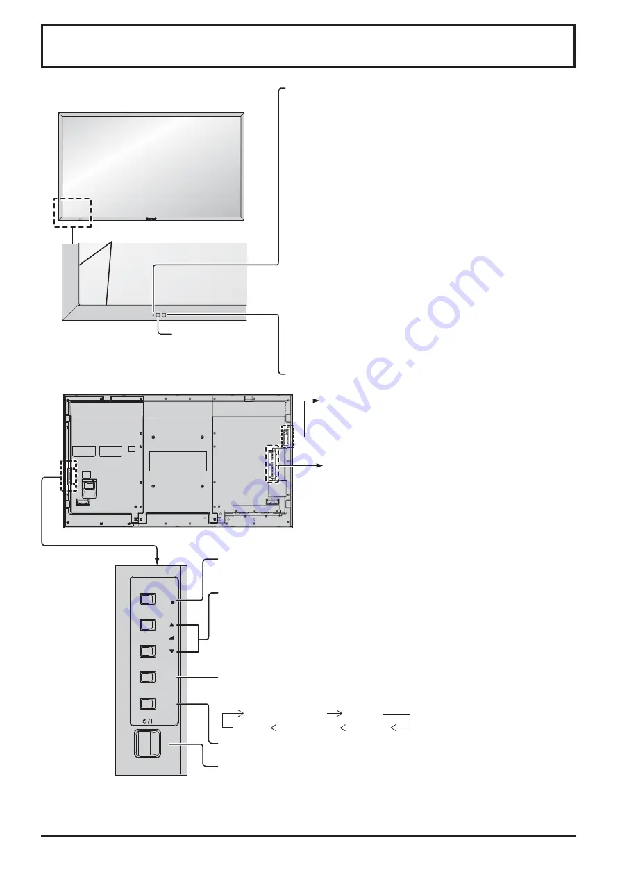
MENU Screen ON / OFF
Each time the MENU button is pressed, the menu screen will switch. (see
page 46)
Normal Viewing
Picture
Sound
Pos. /Size
Setup
Volume Adjustment
Volume Up “+” Down “–”
When the menu screen is displayed:
“+” : press to move the cursor up
“–” : press to move the cursor down
(see page 46)
Remote control
sensor
Main Power On / Off Switch
Brightness Sensor
Detects the brightness in the viewing environment. (see page 63)
Main Unit
Power Indicator
The Power Indicator will light.
• Power-OFF .... Indicator not illuminated (The unit will still
consume some power as long as the power
cord is still inserted into the wall outlet.)
• Standby ........ Red
Orange (When “Slot power” is set to “On” and
Terminal Board is installed. See page 74)
Orange (Depending on the type of the function board
installed, when the power is supplied to the slot)
Orange (When “Control I/F Select” is set to “DIGITAL
LINK/LAN” or “Wireless Network Standby” is set to “On”.
Refer to “Operating Instructions, Network Operations”)
Orange (When “Quick Launch” is set to “On”. See page 59)
• Power-ON ...... Green
• HDMI1 Power management
HDMI2 Power management
......................... Orange (With HDMI1 or HDMI2 input signal. See page 63)
* These functions are not supported by TH-80LFB70E.
• PC Power management (DPMS)
......................... Orange (With PC input signal. See page 63)
• DVI-D Power management
......................... Orange (With DVI input signal. See page 63)
Note:
If the power indicator is orange, power consumption during standby
is generally larger than that of when the power indicator is red.
Enter / Aspect button
(see page 23, 46)
INPUT button (INPUT signal selection)
(see page 20)
SLOT:
Terminal board (optional accessories) insert
slot (see page 4 )
Note:
The upper side slot is for terminal board with 2-slot
width. The terminal board with 1-slot width does not
function when installed in the upper side slot.
Touch panel IR transmission part
Installed on the four sides of the display panel.
USB (VIEWER):
Connect to USB memory. (see page 31)
USB (TOUCH):
When using the “WhiteBoard
Software” from the supplied CD-ROM,
connect the computer via USB cable.
(see page 44)


