background image


r

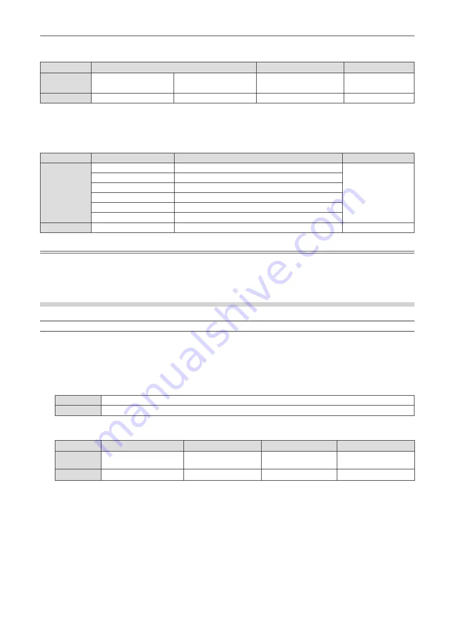
Received data

Header

Data section

Termination symbol

Command 

example

‘0’

0x30

‘0’

0x30

Control command

(ASCII string)

(CR)

0x0d

Data length

1 byte

1 byte

Undefined length

1 byte


f

Example: The projector is powered on


“00001” (CR)


r

Error response

String

Details

Termination symbol

Message

"ERR1"

Undefined control command

(CR)

0x0d

"ERR2"

Out of parameter range

"ERR3"

Busy state or no-acceptable period

"ERR4"

Timeout or no-acceptable period

"ERR5"

Wrong data length

"ERRA"

Password mismatch

Data length

4 bytes

1 byte

Note


f

The projector automatically disconnects from the network immediately after sending the command. Such specifications are made from the 

viewpoint of security, such as prevention of illegal operation of the projector by a malicious third party. To send commands continuously, 

make a request for network connection every time and send it. For details, see “Communication flow between the server and the client” 
(

x

 page 148).

When connecting in non-protected mode

Connection method

This is the connection method when [NETWORK] menu → [NETWORK SECURITY] → [COMMAND PROTECT] 

is set to [DISABLE]. 

1)  Obtain the IP address and port number (Initial set value = 1 024) of the projector and make a request 

for connection to the projector.


f

You can obtain both the IP address and the port number from the menu screen of the projector.

IP address

Obtain from the [NETWORK] menu → [NETWORK STATUS].

Port No.

Obtain from the [NETWORK] menu → [NETWORK CONTROL] → [COMMAND PORT].

2)  Check the response from the projector.

Data section

Blank

Mode

Termination symbol

Command 

example

“NTCONTROL”

(ASCII string)

‘  ’

0x20

‘0’

0x30

(CR)

0x0d

Data length

9 bytes

1 byte

1 byte

1 byte


f

Mode : 0 = Non-protect mode


f

Example: Response during non-protect mode


“NTCONTROL 0” (CR)

ENGLISH


-


147

Chapter 7  Appendix - Technical information

Summary of Contents for PT-TMZ400

Page 1: ...o all the models regardless of suffixes of the Model No z z D for India z z T for Taiwan Before operating this product please read the instructions carefully and save this manual for future use Before...

Page 2: ...ecting 49 Selecting the image input for projection 49 How to adjust the state of the image 51 Adjusting adjustable feet 51 Operating with the remote control 52 Using the shutter function 52 Using the...

Page 3: ...be used 109 Connecting the device 109 Ending the connection with the device 109 Network connection 110 Connecting via wired LAN 110 Connecting with wireless LAN 111 About Presenter Light 115 Web cont...

Page 4: ...interference for Taiwan WARNING This equipment complies with the Class A standard of CNS 15936 This is Class A information technology equipment that may cause radio frequency interference when used i...

Page 5: ...NGEREUSE AU RAYONNEMENT DIRECT OU DIFFUS DES YEUX OU DE LA PEAU Inside of product Notice on laser for Taiwan This projector is the Class 1 laser product that complies with IEC EN 60825 1 2014 1 Bottom...

Page 6: ...pport Projector Contact https panasonic net cns projector This device complies with Part 15 of the FCC Rules Operation is subject to the following two conditions 1 This device may not cause harmful in...

Page 7: ...l shock if the cut off plug is inserted into any 13 amp socket If a new plug is to be fitted please observe the wiring code as shown below If in any doubt please consult a qualified electrician WARNIN...

Page 8: ...tungsberechtigter in der EU Panasonic Testing Centre Winsbergring 15 22525 Hamburg Deutschland Italiano Fabbricato da Panasonic Connect Co Ltd 4 1 62 Minoshima Hakata ku Fukuoka 812 8531 Giappone Impo...

Page 9: ...15 22525 Hamburg N metorsz g Nederlands Geproduceerd door Panasonic Connect Co Ltd 4 1 62 Minoshima Hakata ku Fukuoka 812 8531 Japan Importeur Panasonic Connect Europe GmbH Bevoegde vertegenwoordiger...

Page 10: ...ect Co Ltd 4 1 62 Minoshima Hakata ku Fukuoka 812 8531 Japani Maahantuoja Panasonic Connect Europe GmbH Valtuutettu edustaja EU ssa Panasonic Testing Centre Winsbergring 15 22525 Hampuri Saksa Svenska...

Page 11: ...stances except deliberately staring into the light projected from the projector HD D3 D4 HZ HD D1 D2 HZ r rRisk group The projector is categorized as the risk group 2 when the hazard distance is 1 m 3...

Page 12: ...esult in electric shocks Do not overload the wall outlet If the power supply is overloaded ex by using too many adapters overheating may occur and fire will result Clean the power plug regularly to pr...

Page 13: ...ian If installation is not carried out and secured correctly it can cause injury or accidents such as electric shocks ACCESSORIES Do not use or handle the batteries improperly and refer to the followi...

Page 14: ...sed Doing so can cause damage and burns to clothing z z Strong light is emitted from the projector s lens Do not place objects in front of the lens while the projector is being used Do not block the p...

Page 15: ...nto provocar calor ruptura da blindagem e produzir fogo devido ao curto circuito dos terminais N o incinere nem aque a as baterias elas n o podem ficar expostas a temperaturas superiores a 100 C 212 F...

Page 16: ...ty and licensed to Panasonic Connect Co Ltd 3 the software licensed under the GNU General Public License Version 2 0 GPL V2 0 4 the software licensed under the GNU LESSER General Public License Versio...

Page 17: ...under conditions with a dust level of 0 15 mg m3 PROJECTOR SETUP menu ECO MANAGEMENT LIGHT POWER set to NORMAL and PICTURE menu DYNAMIC CONTRAST set to 2 Compact design light weight and flexible setu...

Page 18: ...Chapter 1 Preparation This chapter describes things you need to know or check before using the projector 18 ENGLISH...

Page 19: ...quipment or the air from the air conditioner does not blow toward the front of the projector f f Places with sharp temperature fluctuations such as near lights studio lamps Doing so may shorten the li...

Page 20: ...the screw holes for ceiling mount on the projector bottom and the setting surface by inserting spacers metallic between them f f Use a torque screwdriver or Allen torque wrench to tighten the fixing s...

Page 21: ...ed A malicious third party may access your personal or corporate network without authorization and engage in the following types of behavior g g Retrieve personal and or secret information information...

Page 22: ...s application software monitors and controls the multiple display devices projector and flat panel display connected to an intranet f f Early Warning Software This plug in software monitors the status...

Page 23: ...al parts When the operating environment temperature is high or in environments where lots of dust cigarette smoke etc is present the replacement cycle of the LCD panel polarizing plate and other optic...

Page 24: ...cking the projector discard the power cord cap and packaging material properly f f Do not use the supplied power cord for devices other than this projector f f For lost accessories consult your dealer...

Page 25: ...on the country For details contact your dealer 4 The suffix of the Model No differs depending on the country Example of the Model No with suffix for AJ WM50 Series AJ WM50E AJ WM50G1 AJ WM50G2 AJ WM50...

Page 26: ...lays the HDMI CEC operation screen x page 90 12 SHUTTER button Used to turn off the audio and video temporarily x page 52 13 MUTE button Used to temporarily mute the projector x page 52 14 STATUS butt...

Page 27: ...can operate the projector by reflecting the remote control signal on the screen The operating range may differ due to the loss of light caused by the properties of the screen f f When the remote contr...

Page 28: ...deteriorate faster if cooling inside the projector is inhibited r r Control panel 6 5 2 7 8 1 3 4 2 1 Power v b button v Standby b Power on Sets the projector to the state where the projector is switc...

Page 29: ...MI IN 2 terminal These are the terminals to input HDMI signal 7 COMPUTER 2 IN terminal This is the terminal to input RGB signals or YCB CR YPB PR signals 8 AUDIO IN 1 terminal AUDIO IN 2 terminal Thes...

Page 30: ...mber at first you need to complete the Initial setting and then after setting the ID number of the projector set the ID number on the remote control About Initial setting please refer to When the init...

Page 31: ...Chapter 2 Getting Started This chapter describes things you need to do before using the projector such as the setup and connections ENGLISH 31...

Page 32: ...unting on the ceiling and projecting from rear Using the translucent screen Menu item Method Menu item Method PROJECTION METHOD AUTO or FRONT CEILING PROJECTION METHOD REAR CEILING Note f f The projec...

Page 33: ...lation of the ceiling mount bracket must be carried out by your dealer or a qualified technician Projected image and throw distance Install the projector referring to the projected image size projecti...

Page 34: ...KEYSTONE and CURVED CORRECTION used together Only CURVED CORRECTION used Vertical keystone correction angle Horizontal keystone correction angle Vertical keystone correction angle Horizontal keystone...

Page 35: ...7 105 0 97 1 23 0 142 1 When DIGITAL ZOOM EXTENDER is set to 80 2 When not using Digital Zoom Extender r r When the screen aspect ratio is 16 9 Unit m Throw ratio When not using Digital Zoom Extender...

Page 36: ...lens center to the image lower end H 2 Screen diagonal SD Projection distance L Maximum distance L 1 27 50 0 50 0 63 0 135 1 52 60 0 60 0 76 0 162 1 78 70 0 71 0 90 0 190 2 03 80 0 81 1 03 0 216 2 29...

Page 37: ...0 8 SD Projection distance L 1 When not using Digital Zoom Extender 0 3774 SD 0 0332 0 3879 SD 0 0342 0 4273 SD 0 0376 When using Digital Zoom Extender 0 3774 SD X 0 0332 0 3879 SD X 0 0342 0 4273 SD...

Page 38: ...re In this case a time base corrector TBC must be connected f f Some computer models or graphics cards are not compatible with the projector f f Connect using an extension device etc when installing t...

Page 39: ...that is compatible with 4K image signal Images may be disrupted or may not be projected when an image signal exceeding the supported transmission speed of the HDMI cable is input f f The HDMI IN 1 ter...

Page 40: ...Chapter 3 Basic Operations This chapter describes basic operations to start with 40 ENGLISH...

Page 41: ...ack of the projector and the power cord connector then insert the connector completely in the correct direction Removing the power cord 1 Confirm that the projector is in standby mode and remove the p...

Page 42: ...MODE is set to NORMAL g g The PROJECTOR SETUP menu ECO MANAGEMENT QUICK STARTUP is set to OFF g g The PROJECTOR SETUP menu AUDIO SETTING IN STANDBY MODE is set to OFF f f When the light source indica...

Page 43: ...s displayed When the projector is switched on for the first time after purchase the INITIAL SETTING screen and the ADMINISTRATOR ACCOUNT screen are displayed in order after the projection starts When...

Page 44: ...on of the screen STANDBY MODE Set the operation mode during standby 2 Press qw to switch the setting f f When all settings are completed proceed to Step 3 3 Press the ENTER button f f Confirm the sett...

Page 45: ...ecuted the INITIAL SETTING screen is displayed after the projection starts When the NETWORK menu INITIALIZE is executed the ADMINISTRATOR ACCOUNT screen is displayed after the projection starts next t...

Page 46: ...R ACCOUNT screen is displayed 10 Press as to select STORE and press the ENTER button f f The confirmation screen is displayed 11 Press qw to select OK and press the ENTER button Note f f For restricti...

Page 47: ...g Note f f The image size may be adjusted with the DIGITAL ZOOM EXTENDER menu However note that the display resolution may decrease when the Digital Zoom Extender function is used For details refer to...

Page 48: ...d on f f Even if the power is turned off by pressing the power v b button the projector consumes power if the power plug is connected to the outlet When the PROJECTOR SETUP menu ECO MANAGEMENT STANDBY...

Page 49: ...COMPUTER 2 Displays the image signals input via the COMPUTER 1 IN terminal or the COMPUTER 2 IN terminal If one input has been selected already the input will be switched every time the button is pres...

Page 50: ...switched with the INPUT SELECT button on the control panel After pressing the INPUT SELECT button the detailed or simple input guide is displayed Detailed input guide example Simple input guide exampl...

Page 51: ...by changing the distance between the screen and the projector f f When the focus is adjusted the projection screen size also changes slightly Depending on the image projection situation repeat Steps 1...

Page 52: ...the shutter function is in use shutter closed f f Even when the shutter function is in use shutter closed the power v b button and input select HDMI 1 HDMI 2 COMPUTER 1 2 NETWORK USB buttons can be op...

Page 53: ...TO SETUP button on the control panel f f The clock phase may shift even if the automatic adjustment is performed In such a case adjust the POSITION menu CLOCK PHASE x page 74 f f When the input signal...

Page 54: ...T x page 69 Using the digital zoom function Only for computer signals input You can enlarge images You can also change the location of the images to be enlarged buttons 1 Press the D ZOOM button D ZOO...

Page 55: ...be performed while confirming the elapsed time or remaining time against the specified time button 1 Press the P TIMER button f f The count is started 2 Press the P TIMER button again f f The count i...

Page 56: ...rojector status can also be displayed using the menu operation Refer to the PROJECTOR SETUP menu STATUS x page 83 for details Using the HDMI CEC function Display the HDMI CEC operation screen button 1...

Page 57: ...ressed within five seconds the ID number returns to its original value before the ID SET button was pressed f f The ID number set on the remote control will be stored unless it is set again However it...

Page 58: ...Chapter 4 Settings This chapter describes the settings and adjustments you can make using the on screen menu 58 ENGLISH...

Page 59: ...TION DISABLE AUTO AUTO ON BLUE DEFAULT LOGO ON SCREEN DISPLAY HDMI SIGNAL LEVEL SCREEN SETTING STARTUP LOGO AUTO SETUP SETTING SHUTTER SETTING SIGNAL SEARCH BACK COLOR P TIMER OTHER FUNCTIONS 3 Press...

Page 60: ...age 60 Resetting adjustment values to the factory default If the DEFAULT button on the remote control is pressed the values adjusted in the menu items are restored to the factory default settings butt...

Page 61: ...LAMP POSITION 24 1 75 1 It depends on the input signal LANGUAGE Details x page 76 DISPLAY OPTION Sub menu item Factory default Page ON SCREEN DISPLAY 77 HDMI SIGNAL LEVEL AUTO 78 SCREEN SETTING 78 STA...

Page 62: ...ISTRATOR ACCOUNT 98 NETWORK SECURITY 100 NETWORK CONTROL 101 PJLink 101 MEMORY VIEWER 103 INITIALIZE 104 Note f f Some items may not be adjusted or used for certain signal formats to be input to the p...

Page 63: ...nly for the computer signals Note f f DICOM is an abbreviation of Digital Imaging and Communication in Medicine and is a standard for medical imaging devices Although the DICOM name is used the projec...

Page 64: ...of the projected image 1 Press as to select SHARPNESS 2 Press qw or the ENTER button f f The SHARPNESS individual adjustment screen is displayed 3 Press qw to adjust the level Operation Adjustment Ad...

Page 65: ...32 32 Press the q button Deemphasizes red in shadow areas BRIGHTNESS G Press the w button Emphasizes green in shadow areas 32 32 Press the q button Deemphasizes green in shadow areas BRIGHTNESS B Pre...

Page 66: ...in value Refer to Setting the light off condition of the light source x page 66 for details Note f f DYNAMIC CONTRAST can be adjusted only when there is a signal input Its settings are effective only...

Page 67: ...he input signal Terminal System format COMPUTER 1 IN terminal COMPUTER 2 IN terminal 480 60i 576 50i 480 60p 576 50p Select AUTO RGB or YCB CR Other video signals Select AUTO RGB or YPB PR HDMI IN 1 t...

Page 68: ...clock frequency MHz Horizontal kHz Vertical Hz 1280x1024 60 1 280 x 1 024 64 0 60 0 108 0 1400x1050 60 1 400 x 1 050 64 0 60 0 108 0 Note f f It may not work properly for some connected external devic...

Page 69: ...TENDER Sets DIGITAL ZOOM EXTENDER to extend the projection distance DIGITAL IMAGE SHIFT Adjusts the image position as necessary when DIGITAL ZOOM EXTENDER is set to anything other than OFF and 100 KEY...

Page 70: ...ayed 7 Press asqw to adjust the position Items Operation Adjustment H Press the w button The image position moves to the right Press the q button The image position moves to the left V Press the a but...

Page 71: ...Press asqw to adjust CORNER CORRECTION UPPER LEFT UPPER RIGHT LOWER LEFT LOWER RIGHT Note f f When the CORNER CORRECTION individual adjustment screen is displaying the individual adjustment screen of...

Page 72: ...Pressing the ENTER button while the individual adjustment screen is displayed can switch to the individual adjustment screen of other items Setting 6POINT CORRECTION Only for PT TMZ400 1 Press as to s...

Page 73: ...up and down adjustment Press the a button The image position moves up Press the s button The image position moves down Horizontal right and left adjustment Press the w button The image position moves...

Page 74: ...is displayed 3 Press qw to adjust the level f f The adjustment values are 0 to 3 ASPECT You can switch the aspect ratio of the image The aspect ratio is switched within the screen range selected in t...

Page 75: ...mages which are not wide screen images are displayed on a wide screen the edges of the images may not be visible or they may become distorted Such images should be viewed as with an aspect ratio of 4...

Page 76: ...RK ENTER SELECT RETURN ASSIGNED FUNCTION DISABLE 1 2 f f Various menus settings adjustment screens control button names etc are displayed in the selected language f f The language can be changed to En...

Page 77: ...remote control while the input guide is displayed Setting OSD POSITION Set the position of the menu screen OSD In conjunction with this setting the display position of the individual adjustment scree...

Page 78: ...IGNAL LEVEL 2 Press qw to switch the item f f The items will switch each time you press the button AUTO Sets the signal level automatically 64 940 Select when the HDMI terminal of an external device s...

Page 79: ...Logo Transfer Software The software can be downloaded from the Website https panasonic net cns projector f f If the PROJECTOR SETUP menu ECO MANAGEMENT QUICK STARTUP is set to ON the startup logo is n...

Page 80: ...tem f f The items will switch each time you press the button BLUE Displays the entire projection area in blue BLACK Displays the entire projection area in black DEFAULT LOGO Displays the Panasonic log...

Page 81: ...d time or remaining time is not displayed when the menu screen is displayed f f The start time becomes 000 00 when MODE is set to COUNT UP f f The start time becomes the value set at TIMER when MODE i...

Page 82: ...als This function can enlarge the projected image 1 Press as to select OTHER FUNCTIONS 2 Press the ENTER button f f The OTHER FUNCTIONS screen is displayed 3 Press as to select DIGITAL ZOOM 4 Press th...

Page 83: ...g function that can be used when multiple projectors are used side by side to enable simultaneous control or individual control via a single remote control 1 Press as to select PROJECTOR ID 2 Press qw...

Page 84: ...e AMBIENT LIGHT DETECTION or SIGNAL DETECTION function 1 Press as to select ECO MANAGEMENT 2 Press the ENTER button f f The ECO MANAGEMENT screen is displayed 3 Press as to select AUTO POWER SAVE 4 Pr...

Page 85: ...f characteristics of each light source conditions of use installation environment etc the runtime may be shorter than the estimation f f Runtime is a time until the luminance of the light source to be...

Page 86: ...s valid f f Proceed to Step 7 when ON is selected 7 Press the ENTER button f f The QUICK STARTUP screen is displayed 8 Press qw to switch VALID PERIOD f f The items will switch each time you press the...

Page 87: ...ton NONE Select the parity condition EVEN ODD Using the control command for the existing projector Set this function when using the control command for previously purchased Panasonic projector to cont...

Page 88: ...on f f The FUNCTION BUTTON screen is displayed 3 Press the ENTER button 4 When the confirmation screen is displayed press qw to select OK and press the ENTER button Note f f You can also cancel the as...

Page 89: ...ER1 Set the audio output for COMPUTER1 input COMPUTER2 Set the audio output for COMPUTER2 input HDMI1 Set the audio output for HDMI1 input HDMI2 Set the audio output for HDMI2 input MEMORY VIEWER Set...

Page 90: ...essage of FILTER COUNTER has reached the set time prompting you to clean replace the air filter is displayed on the projection screen 1 Press as to select FILTER COUNTER 2 Press the ENTER button f f T...

Page 91: ...ch the item f f The devices will switch when multiple CEC compatible devices are connected to one input f f Select the device to operate 6 Press as to select HDMI CEC OPERATION 7 Press the ENTER butto...

Page 92: ...Press qw to select ON 3 Press the ENTER button f f The HDMI CEC screen is displayed 4 Press as to select DEVICE PROJECTOR 5 Press qw to switch the item f f The items will switch each time you press th...

Page 93: ...ng off are disabled Note f f When the SECURITY menu PASSWORD is set to ON the PASSWORD screen will be displayed after selecting INITIALIZE ALL and pressing the ENTER button Enter the security password...

Page 94: ...s to select PASSWORD 2 Press qw to switch the item f f The items will switch each time you press the button OFF Disables the security password entry ON Enables the security password entry Note f f Thi...

Page 95: ...ons ON Disables menu operations Note f f The factory default setting or the setting after executing the PROJECTOR SETUP menu INITIALIZE ALL is set to OFF Set it to ON if necessary f f When MENU LOCK i...

Page 96: ...l buttons DISABLE Disable the operation of all buttons f f When you change ENABLE to DISABLE proceed to Step 5 5 When the confirmation screen is displayed press qw to select OK and then press the ENTE...

Page 97: ...he preferred DNS server address when DHCP is set to OFF DNS2 Enter the alternate DNS server address when DHCP is set to OFF 4 After the setting select OK and press the ENTER button Note f f For the se...

Page 98: ...eb control function Network config page Wireless LAN x page 122 f f A QR code which makes connection setting with a smartphone easier is displayed in WIRELESS LAN page 2 3 To directly connect a smartp...

Page 99: ...press the ENTER button f f The ADMINISTRATOR ACCOUNT screen is displayed 12 Press as to select STORE and press the ENTER button f f The confirmation screen is displayed 13 Press qw to select OK and pr...

Page 100: ...ACCOUNT screen is displayed 15 Press as to select PASSWORD CONFIRM under NEW and press the ENTER button f f The PASSWORD CONFIRM screen is displayed 16 Enter the password entered in Step 13 17 After e...

Page 101: ...ER button f f The NETWORK CONTROL screen is displayed 3 Press as to select an item and press qw to change the setting WEB CONTROL Set to ON to control with the web browser COMMAND CONTROL Set to ON to...

Page 102: ...racters can be entered 9 After entering the password press asqw to select OK and press the ENTER button f f The PJLink PASSWORD screen is displayed 10 Press as to select PASSWORD CONFIRM and press the...

Page 103: ...R input is selected f f For details on how to use the memory viewer function please refer to Projecting with MEMORY VIEWER input x page 107 SET SLIDE Start the slideshow For details on the slideshow s...

Page 104: ...w to switch the item f f The items will switch each time you press the button OFF Displays the image in its original pixels ON Displays the image according to the screen set in the DISPLAY OPTION menu...

Page 105: ...ORD is set to ON the PASSWORD screen will be displayed when INITIALIZE is selected and the ENTER button is pressed Continue your operation after entering the security password set for the projector f...

Page 106: ...Chapter 5 Operation of Function This chapter describes the operation methods of some functions 106 ENGLISH...

Page 107: ...or while data is being read from the USB memory It may cause data loss or data corruption f f Do not leave the USB memory in a place with high humidity or dust f f Do not leave the USB memory in a pla...

Page 108: ...maintaining the aspect ratio f f When the recorded number of pixels is the same as the maximum number of display dot 1 it will neither be enlarged nor reduced so degradation of image quality can be re...

Page 109: ...ill switch between MEMORY VIEWER and NETWORK f f The standby screen is displayed once the input is switched to NETWORK 2 Connect the device with the image transfer application software started to the...

Page 110: ...transfer application software Wireless Projector compatible with the iPad iPhone iPod touch or Android device refer to the website https panasonic net cns projector f f PJLink By using PJLink protoco...

Page 111: ...he computer 2 Perform the network setting following the instruction of your network administrator f f If the projector is in factory default setting you can use it as it is if the network setting of t...

Page 112: ...a smartphone easier is displayed in the network input idle screen To directly connect a smartphone to the projector using the QR code refer to Using the QR code x page 113 f f The SSID IP address wir...

Page 113: ...NETWORK screen is displayed 2 Press as to select NETWORK STATUS and press the ENTER button f f The NETWORK STATUS screen is displayed 3 Press as to switch the displayed screen and display WIRELESS LAN...

Page 114: ...x page 122 r r Operation of a smartphone 1 Start application software of the camera supporting reading of a QR code 2 Read the QR code displayed in the OSD or the network input idle screen with the ca...

Page 115: ...er x page 116 2 Click Download f f The download screen of Presenter Light is displayed 3 Click Download f f The download confirmation screen of the compressed file Presenter Light zip is displayed 4 S...

Page 116: ...go to the website of Crestron Electronics Inc English only URL https www crestron com resources get roomview Computer that can be used for setting A web browser is required to use the web control fun...

Page 117: ...y by starting up multiple web browsers Do not set or control the projector from multiple computers f f Access will be locked for few minutes when an incorrect password is entered three times consecuti...

Page 118: ...you can download the license from the Set up password page that appears when you access the projector Descriptions of items 1 2 3 4 5 6 7 PT TMZ400 1 Page tab Pages are switched by clicking this item...

Page 119: ...re of the projector 12 EXHAUST AIR TEMPERATURE Displays the status of the exhaust air temperature of the projector 13 LIGHT TEMPERATURE1 LIGHT TEMPERATURE2 Displays the temperature status of light sou...

Page 120: ...N Displays the configuration details of wired LAN Basic control page Click Projector control Basic control 1 2 3 5 4 1 INPUT Switches the image input to be projected 2 VOLUME Adjusts the volume level...

Page 121: ...fig 1 Click Network config f f The CAUTION screen is displayed 2 Select the item which you want to change the setting f f The WIRELESS LAN setting can be selected only when the optional Wireless Modul...

Page 122: ...e Back button to return to the original screen The current settings are displayed by pressing the Next button Click the Submit button to update the settings Note f f When you use the Forward and Back...

Page 123: ...set up ECO management set up 1 9 2 3 4 5 6 7 8 1 LIGHT POWER Displays the LIGHT POWER setting 2 AUTO POWER SAVE Sets to ON when setting AMBIENT LIGHT DETECTION and SIGNAL DETECTION 3 AMBIENT LIGHT DET...

Page 124: ...TECT is set to DISABLE connection authentication is not performed making it vulnerable to threats on the network Be aware of the risks before making settings f f For details on how to use the command...

Page 125: ...The default value is 60 minutes In this case another E mail will not be sent for 60 minutes after sending the temperature warning E mail even if it reaches the warning temperature 6 INTAKE AIR TEMPER...

Page 126: ...bmit Updates the settings Contents of E mail sent Example of E mail sent when E mail is set The following E mail is sent when the E mail settings have been established Panasonic projector report CONFI...

Page 127: ...degF PROJECTOR RUNTIME 21 H LIGHT RUNTIME 21 H Current status MAIN VERSION 0 25 SUB VERSION 0 90 LIGHT STATUS LIGHT ON INPUT NETWORK Wired Network configuration DHCP Client ON IP address 192 168 0 105...

Page 128: ...ETWORK CONTROL Crestron Connected TM x page 101 to ON if information prompting users to confirm projector s settings is displayed on the Crestron tools page Set up password page for administrator acco...

Page 129: ...i Monitoring Control Software which uses the communication control via LAN communication with the projector will become impossible if the user name or password for Administrator is changed If the user...

Page 130: ...the change of password Set up password for standard user account The password of the standard user account can be changed 1 2 3 4 1 Old Password Enter the current password 2 New Password Enter the des...

Page 131: ...s downloaded by clicking this item Specify the destination to save and download the license Note f f Provided license is a text file and it is saved in the firmware of the projector in zip format comp...

Page 132: ...I2 input then check that the image from the CEC compatible device is projected correctly Operating the CEC compatible device with the projector remote control You can operate the device using the proj...

Page 133: ...on upon startup of the projector The link control setting of DEVICE PROJECTOR r r When the setting is POWER ON or POWER ON OFF f f While the projector is in standby if the CEC compatible device is tur...

Page 134: ...Chapter 6 Maintenance This chapter describes methods of inspection when there are problems maintenance and replacement of the units 134 ENGLISH...

Page 135: ...n after the measure is taken switch off the projector and remove the power cord plug from the outlet then ask your dealer for repair Temperature indicator TEMP Indicator status Blinking red 3 times Bl...

Page 136: ...damage to the lens surface Air filter unit This section describes the maintenance of the air filter unit that is installed as standard on the projector The air filter unit is the same as the optional...

Page 137: ...air filter unit If it is not attached the projector will suck in dirt and dust causing a malfunction Performing maintenance of the air filter unit Fig 1 Fig 2 1 Wash the air filter unit Fig 1 i Soak...

Page 138: ...ck in dirt and dust causing a malfunction Resetting the air filter counter 1 Turn on the projector 2 Press the MENU button on the remote control or the control panel f f The main menu screen is displa...

Page 139: ...cement Filter Unit Model No ET RFL400 to the projector f f Refer to Attaching the air filter unit x page 138 3 Reset the air filter counter f f Refer to Resetting the air filter counter x page 138 Att...

Page 140: ...set correctly 30 f f Are there any obstructions between the remote control and the remote control signal receiver of the projector 27 f f Is the remote control used beyond its effective operation ran...

Page 141: ...operation noise becomes loud If the internal temperature reaches the abnormal value the indicators will light up or blink 135 f f Is the ambient temperature high 19 f f Is the air filter unit dirty 13...

Page 142: ...ture 2 error 1 F16 Angle sensor error 2 H14 Light temperature sensor 1 error 2 H16 Light temperature sensor 2 error 2 U16 Light temperature 1 warning 1 U18 Light temperature 2 warning 1 F18 Air pressu...

Page 143: ...Chapter 7 Appendix This chapter describes specifications for the projector ENGLISH 143...

Page 144: ...led shutter closed mute function enabled muted AVMT Shutter status query audio output status query 21 Shutter function disabled shutter open mute function enabled muted 30 Shutter function disabled sh...

Page 145: ...disabled Freeze function enabled freeze FREZ Freeze status query 2 LKUP Link up notification xx xx xx xx xx xx Notifies the MAC address when the PJLink communication becomes possible 2 SRCH Projector...

Page 146: ...mination symbol Command example NTCONTROL ASCII string 0x20 1 0x31 0x20 zzzzzzzz ASCII code hexadecimal number CR 0x0d Data length 9 bytes 1 byte 1 byte 1 byte 8 bytes 1 byte f f Mode 1 Protect mode f...

Page 147: ...usly make a request for network connection every time and send it For details see Communication flow between the server and the client x page 148 When connecting in non protected mode Connection metho...

Page 148: ...r no acceptable period ERR5 Wrong data length Data length 4 bytes 1 byte Note f f The projector automatically disconnects from the network immediately after sending the command Such specifications are...

Page 149: ...nnected internally 8 RTS 9 NC Communication conditions Factory default Signal level RS 232C compliant Sync method Asynchronous Baud rate 9 600 bps Parity None Character length 8 bits Stop bit 1 bit X...

Page 150: ...01 response is sent from the projector to the computer f f If an invalid parameter is sent the ER402 response is sent from the projector to the computer f f ID transmission in RS 232C supports ZZ ALL...

Page 151: ...r status query 1 Shutter function on shutter closed Q S Light source condition query 0 1 2 3 Stand by Light source ON control active Light source ON Light source OFF control active VSE Aspect ratio sw...

Page 152: ...CTURE MODE is set to DYNAMIC LIGHT POWER is set to NORMAL DAYLIGHT VIEW is set to OFF and AUTO POWER SAVE is set to OFF PT TMW380 PT TMX380 3 800 lm Contrast ratio 1 3 000 000 1 When PICTURE MODE is s...

Page 153: ...or ECO 24 dB When LIGHT POWER in ECO MANAGEMENT is set to QUIET Operating environment Operating temperature 0 C 32 F to 45 C 113 F 2 3 Operating humidity 20 to 80 no condensation Operation position F...

Page 154: ...lastic Color White Power cord length India 3 0 m 118 1 8 Other countries or regions 2 0 m 78 3 4 Laser Classification Laser Class Class 1 IEC EN 60825 1 2014 Risk Group Risk group 2 IEC 62471 5 2015 W...

Page 155: ...mm inch 71 2 7 16 349 13 3 4 370 14 9 16 240 9 7 16 35 1 3 8 6 1 4 99 3 15 16 88 3 15 32 105 4 1 8 117 4 19 32 73 2 7 8 138 5 7 16 Actual dimension may differ by product ENGLISH 155 Chapter 7 Appendix...

Page 156: ...160 54 0 24 0 1 297 0 l 4096 x 2160 25p 4 096 x 2 160 56 3 25 0 297 0 l 4096 x 2160 30p 4 096 x 2 160 67 5 30 0 1 297 0 l C 640 x 480 60 640 x 480 31 5 59 9 25 2 l l 800 x 600 60 800 x 600 37 9 60 3...

Page 157: ...resolution may not be selected on the computer even if the projector is supporting it Signal name SIGNAL FORMAT Resolution dots Scanning freq Dot clock freq MHz Plug and play compatible signal Horizon...

Page 158: ...x 1024 85 1 280 x 1 024 91 1 85 0 157 5 1366 x 768 60 1 366 x 768 47 7 59 8 85 5 1400 x 1050 60 1 400 x 1 050 65 3 60 0 121 8 1400 x 1050 75 1 400 x 1 050 82 2 75 0 155 9 1440 x 900 60 1 440 x 900 55...

Page 159: ...ation even if the warranty period of the projector has not expired f f Unused products must be removed promptly by a qualified technician f f Use a torque screwdriver or Allen torque wrench to tighten...

Page 160: ...lacement 136 MEMORY VIEWER 103 MEMORY VIEWER input 107 MENU button Projector body 28 Remote control 26 MENU LOCK 95 MENU LOCK PASSWORD 95 Menu Navigation 59 MUTE button Remote control 26 52 N NETWORK...

Page 161: ...tment recovery and recycling of old products and used batteries please take them to applicable collection points in accordance with your national legislation By disposing of them correctly you will he...

Reviews: